
Wednesday, January 4, 2012


Monday, January 2, 2012
New Quad Prop Source

Lucien says:
They are available in the following sizes: 8x4.5, 9x4.7, 10x4.5, 11x4.7 and 12x4.5. There are two different plactic formulations used for these props. The standard ones are made with a fiberglass filled ABS plastic, and are about the same stiffness as an APC Slow-Fly type prop. These are available in Black, Bright Green and Bright Orange in both normal and reverse rotation.
The Hi-Strength versions are made from a carbon fiber filled nylon, and are about 10 times stiffer than the standard props so they really maintain their shape and airfoil under load. These props are only available in black, and have a satin finish to them.
Prices on the props are as follows, normal or reverse pitch is the same price:
Standard Series, Black, Green or Orange:
8x4.5 - $1.50 each
9x4.7 - $1.75 each
10x4.5 - $2.00 each
Carbon Reinforced Series, Black:
8x4.5 - $2.00 each
9x4.7 - $2.25 each
10x4.5 - $2.50 each
11x4.7 - $3.00 each
12x4.5 - $3.50 each
A whole lot of Arduino and Robotics links!
Getting ready to teach an Arduino class, so have a lot of links prepping for that. Instead of giving the impression that this blog has forgotten about flying, I'm posting a bunch of miscellania here.
Timer Stuff
Timer Stuff
- timer1 library. This library is a collection of routines for configuring the 16 bit hardware timer called Timer1 on the ATmega168/328. There are 3 hardware timers available on the chip, and they can be configured in a variety of ways to achieve different functionality.
- SO query with a couple of answers.
AVR Programming
Arduino Tutorials
Clickwheels and Diskdrive Spinners
- some forum post.
- Instructable: HDDJ: Turning an old hard disk drive into a rotary input device (video)
- code: Interfacing › HDDJ:hard drive as scrollwheel/turtable-like input
LarryBot
- larryBot – Arduino robot versions 0.1 to 0.5 lessons learned
- Obstacle avoidance Arduino robot – build your own larryBot (this one with tank treads)
- Control a DC motor with Arduino and L293D chip
- Arduino – Sonic range finder with SRF05
- Arduino: Controlling the Robot Arm
- Micro GearmotorBlocks
- Tamiya 70097 Twin-Motor Gearbox Kit
- Tamiya Gearbox Gear Ratio Comparison
- ebay listing with some good information
- Arduino library to control the DS1307 RTC
Calculators
Docs

Servo Extension Arms for 3D Foamies
Great advice from Leadfeather:
- For good 3D you should have at least +- 45 degrees.
- Cut slits only if you have stiff hinges. If they are already flexible the slits won't help.
- The longer arms are pretty typical, especially for the 5 gram servos.
- Possibly increase the servo travel if your Tx allows. Most computer radios allow you to do this in the "travel adjustment" and also in the "dual rate/expo" set up.
- For me, more throw means I use more expo for nice control response.
- For the HXT 500, Dubro 930 Micro Servo Arm XL
- For the HXT 900, Dubro 932 Micro Servo Arm XL
A couple of ideas for foamy cutout skids
- 1/64 light ply strip 9mm wide 6 in long glued with welder makes a great skid.
- a thin skin of Welder's along the bottom and front lower section of my builds.
- some strapping tape the same width or a tad wider along the edge of the lower fuse.
- Welders, covered by tape.
Quad laser motor balancing
Basic idea: attach mirror to the quad arm, shine a laser beam reflected onto a wall. Vibrations show up as a line, when the reflected later light is a point you're perfectly balanced. Very clever!
Layer Lens -- GoPro lens cover


Sunday, January 1, 2012
Build Update -- Arcticopter III


Props: 10x4.5. MontoRC props have been really good so far and need minimal balancing. They're pretty stiff as well.
Battery: I've had good luck with Zippy 3S/2200/40Cs. flying sedately, 25Cs weren't too bad.
Weight: 714g without battery, 915g with.


Look here to see how I cover the electronics.


Saturday, December 31, 2011
ArudpilotMega2 + Arcticopter III maiden
will type some more later, but I'm really pleased with how it went!
Didn't intend to take any pics (the hat portion of ye olde hatcam being misplaced), but things went so well I was able to fly one-handed and hold the iphone in the other hand. Beautiful!!
From the air. I hadn't planned on doing this either, but things were so smooth I taped the GoPro and sent it off. Simple mode is going to be a Godsend for arial photography.
Spinning one-handedly. This is cut from the first video, but it's so unique and impressive I wanted to hilight it by itself.
Didn't intend to take any pics (the hat portion of ye olde hatcam being misplaced), but things went so well I was able to fly one-handed and hold the iphone in the other hand. Beautiful!!
From the air. I hadn't planned on doing this either, but things were so smooth I taped the GoPro and sent it off. Simple mode is going to be a Godsend for arial photography.
Spinning one-handedly. This is cut from the first video, but it's so unique and impressive I wanted to hilight it by itself.
Using a DSO Nano oscilloscope to troubleshoot APM
An oscilloscope turned out to be a pretty handy debugging tool when trying to troubleshoot my APM2 ESC problem. Here's a shakycam showing how I used mine to verify the problem was with the ESC and not with the APM2.
APM2 indoor maiden and simple mode test
I got everything together last night and couldn't wait until the morning to go out, so I took a quick flight in the basement. Stability was pretty good. I made a quick video of simple mode too.
Thursday, December 29, 2011
The Unbearable Lightness of Universal Serial Busses

- Apple iPhone
- proprietary -- Casio Camera
- Micro A (?)- Ardupilot Mega 2
- Type B -- Arduino Uno
- proprietary -- Panasonic Lumix camera
- FTDI programmer -- Arduino [*]
- mini-B lots and lots of stuff
- update: AVR programmer

[*] The FTDI adaptor probably shouldn't count, since it connects to a Mini-B cable, but it's a serial thing I have around. Of course if I mention the FTDI programmer I should also mention the AVR programmer for completeness. It comes in two flavors as well; 10 pin and 6 pin.


Update: now added a lightning connector for iphone 5.
Wednesday, December 28, 2011
DS1307 Real Time Clock

- geiliable-store listing
- i.control listing
- technical notes and arduino library
Quad EPS blade protection

It would be great to be able to provision a homemade quad with something like this.
DSO Nano 2 Oscilloscope notes

Here's some links for the thing:
- product page at seedstudio.com
- product manual (pdf)
- wiki docs
- forum
- early review, linked on hackaday
Handy Glue Tip

I have a box for all glues and adhesives... I put a piece of old foam in the bottom, and made a few holes and slots to hold opened containers with the opening down.

Monday, December 26, 2011
xbee attempted unbricking and troubleshooting


Here's shakycam documentation of the procedure. It's not working, so suspecting other xbee problem.
Sunday, December 25, 2011
CF Reinforcement for Skywalker Wings
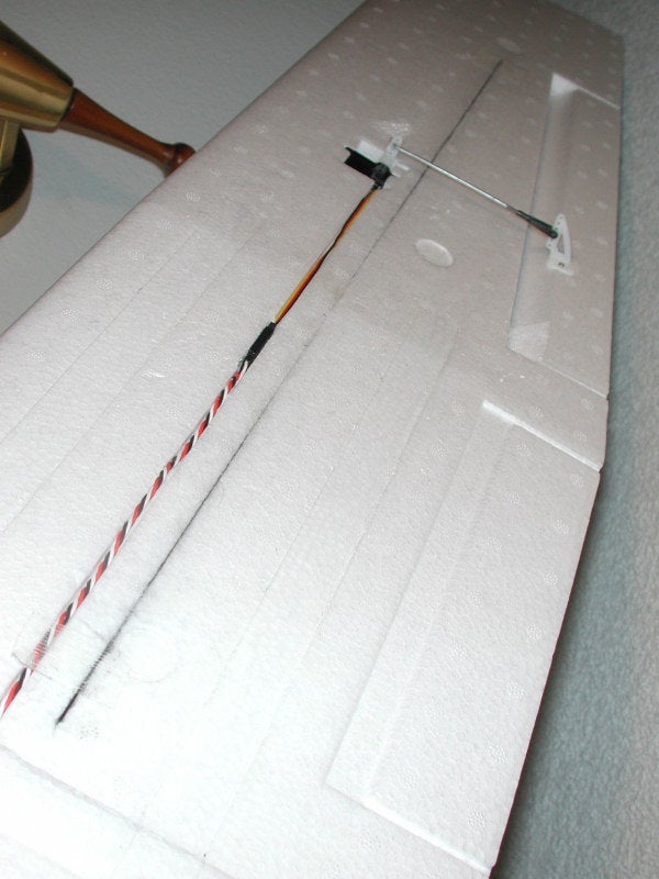
Basic Idea:
- Cut four 36'' ribbons, two pieces for each wing
- Cut into top and bottom of wing, one directly above the other.
- Glue in edgewise.
- Size: 0.8x6mm
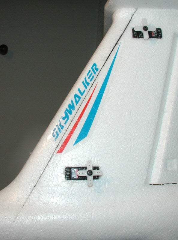
Do the same to the vertical stabilizer.
Daemon describes it:
Here's a flight with the reinforced wings:
Daemon describes it:
I use a long straight edge and X-acto blade to cut the slot using my finger on the side of the blade as a depth gauge (something you can't do with a soldering iron tip) and then expand the slot slightly with the tip of a screwdriver. 0.8x6mm ribbon spar installed edgewise into the wing on the bottom. Another one just like it on top.
Here's a flight with the reinforced wings:


Saturday, December 24, 2011
H Gantry design


Friday, December 23, 2011
My Farm Fresh Quad Helmet

Nylon 6/6 Male-Female Standoff 4-40
1/2" Body Length,
3/16" Male and Female Thread Lengths,
White (Pack of 100)
http://www.amazon.com/gp/product/B00...ms_ohs_product

I attached the standoffs to the frame, and colored the tops with a Sharpie to align the holes. I handheld a drill bit to cut the holes in the plastic.

One nice feature of the nylon threads is that they will break before anything else. If you break the threads off of a standoff, it becomes a perfect candidate for being the top screw.

Thursday, December 22, 2011
Some Spectrum Analysis and RF Resources from Agilent

arocholl reports:
Agilent is starting a webcast series of sessions about Spectrum Analysis and RF basics. It may be of interest of (most) RF Explorer users and RF enthusiast out there.
RF Back to Basics: Part 1 - Signal Analysis on Jan 25, 2012.
For those of you who don't know, Agilent is the spinoff of HP for testing instruments and RF devices, a worldwide reference in RF for many decades. Besides that, they are the actual guys implementing the closest vision Bill and Dave had about their company when they created HP in the 30's, nothing close to main HP brand these days.
I recommend all the Agilent general guide I recommended to many people already. The link may get invalid anytime as it is internal to Agilent, but if it doesn't work just look for the famous "Application Note 150", the "5952-0292EN.pdf" document or simply "Spectrum Analysis Basics" within the Agilent site.
The Application Note 150 seems to be very well known. I've downloaded it and started reading it. A lot of it's going over my head so far!
Monday, December 19, 2011
Ritewing Zephyr II + Ardupilot Maiden


NTM Prop Drive 35-36A 1800
Turnigy Trust 70A
10x6 prop
Ground Video. This contains most of the flying modes, takeoffs, landings, and low passes. I'll make a trimmed down version later if this one seems repetitive.
Thursday, December 15, 2011
The IOCCC Flight Simulator

IOCCC Flight Simulator runs on Unix-like systems with X Windows. As per contest rules, it is in the public domain."

Sunday, December 11, 2011
Adding Failsafe to the Turnigy 9x transmitter with Autopilot
some quick notes:
Problem
The Turnigy 9x doesn't have a failsafe function when used with the 2.4ghz receiver. Instead, when the radio signal is lost, the receiver "freezes" all channel signals to the last received value.
Idea
Add a heartbeat function.
Transmitter
Pick a channel, alternate between high and low PWM signals over some period. As a concrete example, on channel 7 transmit a 1200 ms followed by an 1800 mhz signal, each for 1000 ms.
We can upgrade the Turnigy 9x to use er9x and add the code there.
Autopilot
In the arduino software, we can add a check in the 1 hz event loop. Compare the current values with the previous values, and save the current values for the next check. If after some number of comparisons we don't detect a change in any values, invoke the failsafe routine.
Notes
Problem
The Turnigy 9x doesn't have a failsafe function when used with the 2.4ghz receiver. Instead, when the radio signal is lost, the receiver "freezes" all channel signals to the last received value.
Idea
Add a heartbeat function.
Transmitter
Pick a channel, alternate between high and low PWM signals over some period. As a concrete example, on channel 7 transmit a 1200 ms followed by an 1800 mhz signal, each for 1000 ms.
We can upgrade the Turnigy 9x to use er9x and add the code there.
Autopilot
In the arduino software, we can add a check in the 1 hz event loop. Compare the current values with the previous values, and save the current values for the next check. If after some number of comparisons we don't detect a change in any values, invoke the failsafe routine.
Notes
- Is the timing fine-grained enough? If not, we can increase the frequency of the checking rate.
- Open source is wonderful.
Update: some discussion of this idea over at the 9x forums.
Saturday, December 10, 2011
Microdan motor for EZ* and related planes

weight: 34g, cost $55
APC 5x5, 21175rpm, 10.9V, 22A, 22oz thrust.
APC 6x4, 19900rpm, 10.7V, 25A, 25oz thrust.
APC 7x4, 16300rpm, 10.2V, 36A, 36oz thrust.
APC 7x5, 15200rpm, 10.1V, 40A, 36oz thrust.
Microdan has a video of it flying in a Hawk Sky:
Friday, December 9, 2011
Elevon Gyro Stabilization
Scott Page has an interesting post on rcgroups where he has mounted gyros on a superfly.
It seems like this couldn't be done without moving the elevon mixing onto the plane, since there's not a direct correlation between axial pitch and roll movement and the control surfaces. The trick is to put two gyros mounted at 45 degrees relative to the front of the plane, and connect the gyros to the servos on the opposite side of the frame.
By doing this, both servos react to pitch and roll, and feed their corrections to the proper (opposite) elevon.
He put a video up with the results of his experiments. He also talks about rate and AVCS (heading hold) modes and their use in fixed wing flight. Executive summary: use rate.
It seems like this couldn't be done without moving the elevon mixing onto the plane, since there's not a direct correlation between axial pitch and roll movement and the control surfaces. The trick is to put two gyros mounted at 45 degrees relative to the front of the plane, and connect the gyros to the servos on the opposite side of the frame.
By doing this, both servos react to pitch and roll, and feed their corrections to the proper (opposite) elevon.
He put a video up with the results of his experiments. He also talks about rate and AVCS (heading hold) modes and their use in fixed wing flight. Executive summary: use rate.
Sunday, December 4, 2011
My SparkFun Signature Edition Solder Fan


If I would have had a spare 3-pin or 4-pin JST-XH I would have used that, so that it could have been powered off of any battery's balance port.
Here it is in action, shot with genuine shakycam:
Friday, December 2, 2011
Troubleshooting my xbee
Here's the system I've got:
https://store.diydrones.com/Xbee_Telemetry_kit_p/kt-telemetry-xbee.htm
It's got an XtreamBee Board, an XtreamBee USB Adapter, a matched pair of xbee modules, and all the bits needed to get things set up.
It was working before:
http://eastbay-rc.blogspot.com/2011/10/first-test-of-apm-auto-mode-drone.html
http://eastbay-rc.blogspot.com/2011/10/xbee-apm-overview.html
 And now it's not working.
symptom: The blue power light comes on on both sides, but the Rx/Tx lights don't come one, and the ground station can't make a connection.
I went ahead and fixed the problem I had where the xbee was soldered inside the socket. You can see one of the pins has a glob of solder on the side. It was obvious which pin it would be, as the connection for the socket had a "sucked in" look instead of a "dimpled hershey kiss" look, from where the solder had been pulled into the socket. Heating the socket leg from the bottom allowed the xbee to be pulled out nicely.
 This allowed me to get both xbee modules attached to the PC and get this information, which seems to verify that the two xbee units are functional (at least in talking to the PC), and that the xbee pro unit is likewise functional.
Likewise, both xbee modules respond to +++ and AT commands from a terminal session.
So, I'm reasonably confident that those three pieces are OK. What to do next? How to verify the xtremebee board?
I'm going to solder some new headers onto the xbee remote carrier, although testing the continuity with a multimeter showed that the pins were all making contact.
I can't find anybody that's a real xbee guru to advise me on this. If I ever get these working again, I am going to really study these things until I understand them really well. My xbee skillz will be my ticket to fame and fortune!
https://store.diydrones.com/Xbee_Telemetry_kit_p/kt-telemetry-xbee.htm
It's got an XtreamBee Board, an XtreamBee USB Adapter, a matched pair of xbee modules, and all the bits needed to get things set up.
http://eastbay-rc.blogspot.com/2011/10/first-test-of-apm-auto-mode-drone.html
http://eastbay-rc.blogspot.com/2011/10/xbee-apm-overview.html

symptom: The blue power light comes on on both sides, but the Rx/Tx lights don't come one, and the ground station can't make a connection.
I went ahead and fixed the problem I had where the xbee was soldered inside the socket. You can see one of the pins has a glob of solder on the side. It was obvious which pin it would be, as the connection for the socket had a "sucked in" look instead of a "dimpled hershey kiss" look, from where the solder had been pulled into the socket. Heating the socket leg from the bottom allowed the xbee to be pulled out nicely.
 This allowed me to get both xbee modules attached to the PC and get this information, which seems to verify that the two xbee units are functional (at least in talking to the PC), and that the xbee pro unit is likewise functional.
Likewise, both xbee modules respond to +++ and AT commands from a terminal session.
So, I'm reasonably confident that those three pieces are OK. What to do next? How to verify the xtremebee board?
I'm going to solder some new headers onto the xbee remote carrier, although testing the continuity with a multimeter showed that the pins were all making contact.
I can't find anybody that's a real xbee guru to advise me on this. If I ever get these working again, I am going to really study these things until I understand them really well. My xbee skillz will be my ticket to fame and fortune!
Thursday, December 1, 2011
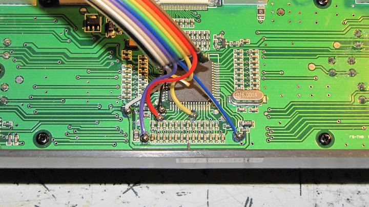
er9x upgrade notes

I'm going to gird my loins (such as they are) and give it a go. I'll update later, but here's a few links on doing this. All of them are by Richard Mrázek, the Michaelangelo of er9x.

cable installation video.
written instructions.
photos of upgrade.
Software Installation
Subscribe to:
Posts (Atom)