No PPM Encoder? Make your own with Arduino pro mini
BuzzsArduinoCode/PPM_Encoder.h at master · davidbuzz/BuzzsArduinoCode
PPMEncoder - Arduino Libraries
Friday, June 26, 2020
Wednesday, June 17, 2020
RC Groups - View Single Post - FRSKY Taranis "How to" Thread
Capturing a double-pull of a momentary switch
Thought I'd share this snippet for capturing a double-pull of a momentary switch. Applications include anywhere a 'safe' switch is required, for example for arming a motor or u/c operation.
Operation:
Pull SH twice within a 1.5 second window. The second pull is captured as an edge in L3.
Code
Operation:
Pull SH twice within a 1.5 second window. The second pull is captured as an edge in L3.
Code
L1 Edge(L02, [0:instant]) Duration(1.5s)
L2 ( Edge(SH-down, [0:instant]) )
L3 L01 AND L02
How it works
- Pulling SH generates an edge in L2, which cascades to L1 a clock tick later.
- Because an edge is true for just a single clock tick, L3 is true only from the second pull. This must be within the time period set in L1.Duration (1.5 secs).
Simple demo - each double-pull toggles a sticky switch:
L4 Sticky(L03, L03)
Tuesday, June 16, 2020
FrSky D4R-II upgrade to D16 protocol
Courtesy of Mike Blandford, of course!
FrSky D16 firmware for D8 receivers - RC Groups
RC Groups - View Single Post - FrSky D16 firmware for D8 receivers
And from Midilic...
FrSky D4R-ii – components, layout, and pinout – fishpepper.de
RC Groups - View Single Post - DIY FrSky TX/RX Modules
FrSky D16 firmware for D8 receivers - RC Groups
RC Groups - View Single Post - FrSky D16 firmware for D8 receivers
And from Midilic...
FrSky D4R-ii – components, layout, and pinout – fishpepper.de
RC Groups - View Single Post - DIY FrSky TX/RX Modules
PrusaSlicer: Removing unused system system settings
In {Print, Filament, Printer} Settings, for each systems setting you want to keep:
- save a copy with your own name, e.g. "marhar PLA"
Now rename PrusaResearch.ini to PrusaResearch.ini.SAFE in the vendors directory.
On Mac, that's Library/Application Support/PrusaSlicer/vendor
Sunday, June 14, 2020
FrSky SxR Gains
Mike Blandford confirms:
In auto-level mode, the individual gains set using the script affect the amount of servo movement output to get to level. The channel 9 gain affects the speed of the servo response..
Saturday, June 13, 2020
Wednesday, June 10, 2020
Tuesday, June 9, 2020
Viewing Wyze Cam on Computer
tl;dr: Wyze supports RTSP with a bit of effort.
Directions and download here:
https://support.wyzecam.com/hc/en-us/articles/360026245231-Wyze-Cam-RTSP
Directions and download here:
https://support.wyzecam.com/hc/en-us/articles/360026245231-Wyze-Cam-RTSP
- Download the firmware
- Boot Cam with firmware on SD card. It will take 3-4 minutes to install.
- In your phone app, Settings / Advanced Settings / RTSP
- Turn on RTSP toggle
- Set name and password, click Generate URL
- Watch with VLC
Monday, June 8, 2020
Reference: "Blue Pill" STM32F103
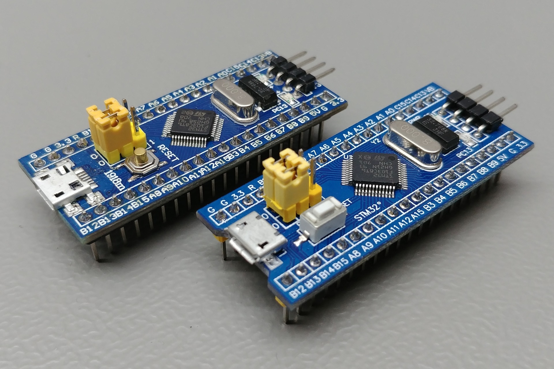
https://stm32-base.org/boards/STM32F103C8T6-Blue-Pill
- Warning: This board may have a wrong value of resistor on the USB D+ pin. Instead of a 1.5kΩ it has either a 10kΩ or 4.7kΩ resistor. This can be solved by replacing the resistor with the right value.
- R10 should be a 1.5kΩ.
References
- Easy & Powerful Arduino Alternative? STM32 Beginner's Guide - YouTube
- LeafLabs Documentation Index — Maple v0.0.12 Documentation
- Getting Started with STM32F103C8T6 STM32 Development Board (Blue Pill) using Arduino IDE: Blinking LED
- Enabling USB on a Blue Pill • JeeLabs
- [STM32]: Overcoming wrong pullup resistor at D+ in blue pill
- Installing the STM32 USB Bootloader, Easily! [SEE DESCRIPTION] - YouTube
Sunday, June 7, 2020
Reference: Geekcreit® 375pcs 3MM 5MM LED
https://www.banggood.com/Geekcreit-375pcs-3MM-5MM-LED-Light-Emitting-Diode-Beads-Resistance-Lights-Kits-Bulb-Lamp-p-1027601.html
Current : 20mA
Voltage: 3V
Color: RED, BLUE, YELLOW, GREEN, WHITE
Total Quantity: 375pcs
Packed in a box
375pcs Five Colors 3mm,5mm Round Bright Light LED Assortment Kit
| |||||||
Color
|
Size
|
Wavelength
(nm)
|
Voltage
(V)
|
Current
(mA)
|
Intensity
(mcd)
|
Lens Color
|
Quantity
|
Red
|
3mm
|
620-630
|
1.9-2.1
|
20
|
3000-4000
|
red
|
50pcs
|
Red
|
5mm
|
620-630
|
2.8-3.1
|
20
|
4000-5000
|
red
|
25pcs
|
Yellow
|
3mm
|
580-590
|
1.9-2.1
|
20
|
5000-6000
|
yellow
|
50pcs
|
Yellow
|
5mm
|
580-590
|
2.8-3.1
|
20
|
4000-5000
|
yellow
|
25pcs
|
Green
|
3mm
|
570-573
|
3.2-3.4
|
20
|
10000-12000
|
green
|
50pcs
|
Green
|
5mm
|
570-573
|
3.0-3.4
|
20
|
12000-14000
|
green
|
25pcs
|
White
|
3mm
|
610-620
|
1.8-2.2
|
20
|
3000-4000
|
clear
|
50pcs
|
White
|
5mm
|
500-620
|
3.0-3.2
|
20
|
12000-14000
|
clear
|
25pcs
|
Blue
|
3mm
|
460-470
|
3.2-3.4
|
20
|
3000-4000
|
blue
|
50pcs
|
Blue
|
5mm
|
460-470
|
3.0-3.4
|
20
|
5000-6000
|
blue
|
25pcs
|
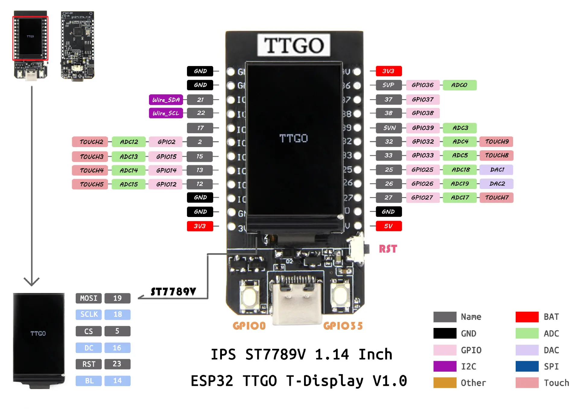
Reference: TTGO ESP32 1.14 Inch LCD LILYGO
On Banggood.
Demo: https://github.com/Xinyuan-LilyGO/TTGO-T-Display
Random notes for the BG page:
IPS ST7789V 1.14 Inch has 135x240 pixel
Display has 340x240 pixel resolution
LCD resolution 240x135
Driver ST7789 (uncomment #define ST7789_DRIVER in User_Setup.h)
Color order Blue-Green-Red (uncomment #define TFT_RGB_ORDER TFT_BGR in User_Setup.h)
Device TTGO_T_Display (uncomment #include in User_Setup_Select.h)
the display seems to require its own graphic library, on github:
github.com/Xinyuan-LilyGO/TTGO-T-Display
github.com/Bodmer/TFT_eSPI
Q:Is the SPI bus accessible for other sensors (other than the display)?
A : VSPI default pins are connected to display and are not available on the headers. HSPI by default uses GPIO 12 to 15. Unfortunately GPIO14 (CLK) is apparently also used by the display BL function. So I assume you will need to remap 14 to another pin to get CLK. (I have not tried this).
Seems to be a difference in this regard between version 1.0 and 1.1. The board I received says V1.1 in silkscreen. According to the pin-out for this version on GitHub GPIO4 (not GPIO14 as indicated above) is used for BL.
Battery-Molex-Pico-1_25mm
Use this library for the display: github Bodmer TFT_eSPI
Look on github for Tetris Clock and "TTGO_example", you will find a library and example I wrote for this board. It has an explanation page that shows how the board looks when running it.
What pins provide me with access to the serial port? TX / RX?
A: A "standard" ESP32 has more pins, the default pins are 3 (Rx) and 1 (Tx) for Serial(0), 9 (Rx) and 10 (Tx) for Serial1, and 16 (Rx) and 17 (Tx) for Serial2. As you can see, with the limited number of pins on this TTGO board, none of them are there. But the good news is that the "Serial.begin" function has an option to change the pins! By using "Serial2.begin(9600, SERIAL_8N1, 25, 26);" you have the Serial2 port on pins 25 (Rx) and 26 (Tx). I tested this today, it's working like a charm!. It's NOT working on pins 37 and 38 (and maybe other pins), but it IS working on pins 25, 26, 27 !!!
This board is an 'ESP32 dev board' and it can be used with the arduino IDE but because it isn't an arduino you'll need to configure the IDE with the new board by adding an 'additional board manager url' to arduino preferences.
Some details of how to do this are here: youtube mBaS3YnqDaU
The board comes loaded with the arduino sketch from here:
Search github Xinyuan-LilyGO TTGO-T-Display
There is a good youtube vid explaining it a little here: youtube qj9dN-Ginxc
The above is a great intro into how to use the 320x240 display and even makes use of the two buttons near the usb port to show voltage and scan for wifi networks.
https://github.com/Xinyuan-LilyGO/TTGO-T-Display/blob/master/schematic/ESP32-TFT(6-26).pdf
----
install quick notes from https://www.youtube.com/watch?v=UE1mtlsxfKM
Arduino / Preferences / Board manager url: https://dl.espressif.com/dl/package_esp32_index.json
Library / Boards / Board manager: esp32
Tools / Board / TTGO Lora32-OLED V1
File / Examples / ESP32 / ChipID / ChipID ESP32 Chip ID = FCB5F9AB6224
Tools / Manage Libraries... / install tft_eSPI by bodmer
edit libraries/TFT_eSPI/User_Setup_Select.h
//#include <User_Setup.h> // Default setup is root library folder
#include <User_Setups/Setup25_TTGO_T_Display.h> // Setup file for ESP32 and TTGO T-Display ST7789V SPI bus TFT
File / Examples/ TFT_eSPI/examples/Generic/alphaBlend_Test
(base) ArduinoBase $ mkdir tools
(base) ArduinoBase $ mv ~/Downloads/ESP32FS tools
restart Arduino
Tools / ESP32DataUploader
Tools / Manage Libraries... / jpegdecoder by bodmer
File / Examples / JPEG Decoder / Other_Libraries / SPIFFS_Jpeg
Tools / ESP32DataUploader
Using the Tiltmeter
Setup
Be sure you have run the self-test to set level and stick travel.
Depending on servo installation, pitch may be reversed. That's indicated in parentheses below.
Set gain to maximum, it will make for largest pitch variation.
Ailerons
Moving stick to left is correction for roll right. Left aileron moves up.
Move stick to left. Note audio-pitch goes up (or down).
Hold plane, twitch right wing down. You should hear audio-pitch up (or down).
Twitch left wing down. You should hear audio-pitch down (or up).
Moving stick to left is correction for yaw right. Rudder moves left.
Move stick to left. Note audio-pitch goes up (or down).
Hold plane, twitch noseto right. You should hear audio-pitch up (or down).
Twitch nose to left. You should hear pitch down (or up).
Elevator
Moving stick back is correction for pitch up. Elevator moves down.
Move stick down. Note audio-pitch goes up (or down).
Hold plane, twitch nose down. You should hear audio-pitch up (or down).
Twitch nose up. You should hear audio-pitch down (or up).
Pitch up = Left aileron up
Pitch up = Elevator up
Pitch up = Rudder left
Ailerons
Rudder
(note) I typed the above because my brain gets confused when I tune planes with servos reversed. Maybe I should add a reversing button to the tiltmeter so that I can match my brain thinking, which is
Friday, June 5, 2020
OctoPrint: Turning on an LED during printhead heating
I do this so I can more easily inspect the printhead for ooze, etc.
OCTO 22 /home/pi/scripts/led-off
$ cd /home/pi/scripts
$ cat led-on.c
void main()
{
system("echo 23 >/sys/class/gpio/export");
system("echo out >/sys/class/gpio/gpio23/direction");
system("echo 1 >/sys/class/gpio/gpio23/value");
}
$ cat led-off.c
void main()
{
system("echo 0 >/sys/class/gpio/gpio23/value");
system("echo 23 >/sys/class/gpio/unexport");
}
$ make led-on led-off
(ignore warnings)
$ sudo chown pi.gpio led-off led-on
$ls -l led-on led-off
-rwxr-xr-x 1 pi gpio 7984 Jun 5 20:33 led-off
-rwxr-xr-x 1 pi gpio 7984 Jun 5 20:33 led-on
Mine looks like this:
G28 W ; home all without mesh bed level
OCTO21 ; turn on external light
G1 Z30 ; raise printhead for visual inspection
M109 S[first_layer_temperature] ; wait for extruder temp
M190 S[first_layer_bed_temperature] ; wait for bed temp
OCTO22 ; turn off external light
Install OctoPrint plugin "GCODE System Commands"
Configure Plugin
OCTO 21 /home/pi/scripts/led-onOCTO 22 /home/pi/scripts/led-off
Use This Code
$ cd /home/pi/scripts
$ cat led-on.c
void main()
{
system("echo 23 >/sys/class/gpio/export");
system("echo out >/sys/class/gpio/gpio23/direction");
system("echo 1 >/sys/class/gpio/gpio23/value");
}
$ cat led-off.c
void main()
{
system("echo 0 >/sys/class/gpio/gpio23/value");
system("echo 23 >/sys/class/gpio/unexport");
}
$ make led-on led-off
(ignore warnings)
$ sudo chown pi.gpio led-off led-on
$ls -l led-on led-off
-rwxr-xr-x 1 pi gpio 7984 Jun 5 20:33 led-off
-rwxr-xr-x 1 pi gpio 7984 Jun 5 20:33 led-on
Add OCTO commands to to your slicer gcode template
(for Prusa-Slicer, in Printer Settings/Custom Gcode/Start GCode).Mine looks like this:
G28 W ; home all without mesh bed level
OCTO21 ; turn on external light
G1 Z30 ; raise printhead for visual inspection
M109 S[first_layer_temperature] ; wait for extruder temp
M190 S[first_layer_bed_temperature] ; wait for bed temp
OCTO22 ; turn off external light
Thursday, June 4, 2020
Raspberry Pi Blink in shell
#!/bin/sh
# release the pin on exit
trap 'echo 0 >/sys/class/gpio/gpio23/value;echo 23 >/sys/class/gpio/unexport' 0
echo 23 >/sys/class/gpio/export
echo out >/sys/class/gpio/gpio23/direction
while true; do
echo 1 >/sys/class/gpio/gpio23/value
sleep 1
echo 0 >/sys/class/gpio/gpio23/value
sleep 1
done
# for input:
# echo 23 >/sys/class/gpio/export
# echo in >/sys/class/gpio/gpio23/direction
# read value:
# cat /sys/class/gpio/gpio23/value
# release a pin
# echo 23 >/sys/class/gpio/unexport
Troubleshooting SiLabs Driver on Mac notes
tl;dr:
Looking for this device;
Do you have the driver software installed?
Is the driver loaded?
Loadin the driver:
This does something:
watch console.app and plug device in.
- 99% chance it's a USB cable problem.
- If you're a manufacturer, blah blah major and minor device numbers
Looking for this device;
- /dev/SLAB_USBtoUART
Do you have the driver software installed?
- find /Library/Extensions/SiLabsUSBDriver.kext
Is the driver loaded?
- kextstat | grep -i silabs
Loadin the driver:
- sudo kextload /Library/Extensions/SiLabsUSBDriver.kext
This does something:
- ioreg -p IOUSB -l
watch console.app and plug device in.
Subscribe to:
Posts (Atom)