Thursday, July 31, 2014

ArrBot: Assembling the Arduinos

Assemble The Arduino Micro

Solder the male pins down each long row.
  • Put the pins in the breadboard.
  • Long end of pins go into the breadboard.
  • Line up the Arduino Micro so that it sits on the pins.
  • CPU goes on top.
Assemble The Arduino Mini

Solder the male pins down each row.  Same as for the Micro.

Solder the end pins.
  • Those are the 90 degree pins.
  • They go into the 6 through holes on the short end.
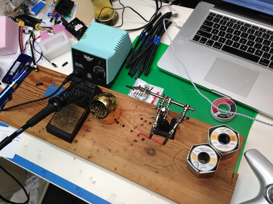
  • Use the helping hands.
  • Flip the board over, the CPU should be on the bottom.
  • The short end of the 90 degree pins should come through the holes.

ArrBot Parts List

Here's a cut and paste.  Sorry it's so ugly... I'll clean it up, but I wanted to get the parts available for people following along on the web.


ArrBot Class 2 Notes

Today's class will consist of of setting up your Arduino environment, testing the Arduinos we made last time, and making "continous rotation" servos.

Syllabus: http://eastbay-rc.blogspot.com/2014/07/arrbot-syllabus.html

Bring:
  • Soldering stuff
  • Laptop computer, if you have it
  • USB "Micro B" cable to fit your Arduino
  • Tiny #000 Phillips screwdriver (fits tiny servo screws), if you have one.
  • Small tweezers, if you have them.
  • Bring extra tools if you have them and don't mind sharing.

Wednesday, July 30, 2014

Soldering: Some Through-hole Counterexamples

 Here's the first row of pins by a beginning student.  Note that the plating on this board is pretty minimal.
Problem: Incomplete solder joint on D, E.
Cause: not enough solder fed into the joint.
Solution: Feed enough solder to make a nice Hershey's Kiss shape.
Problem: Middle joint flows into adjoining through-hole.
Cause: Too much solder, or soldering iron crossing two holes.
Solution: Make sure your iron is firmly contacting just one hole/pin, and don't feed too much solder.


After just a couple of rows, the joints are good, and look like Hershey's Kisses.


Problem: "Mushroom" Top, no connection to through-hole.  Look at the third from the right.
Cause: Not making contact between the through-hole and the soldering iron.  The plating is pretty minimal -- this is more symptomatic of Cheap PC board construction.  In our previous class we had some higher quality boards and didn't see this problem.
Solution: Bear down on the iron, to make sure there's a good concurrent touch between the pin and the through-hole.

And here's the same board, after cleanup.  Textbook job!  If you have a wedge or screwdriver tip, be sure the flat edge is touching both the pin and the pad.


blogodex = {"toc" : ["Soldering", "Soldering Class"]};

Tuesday, July 29, 2014

Controlling AS3X with GEAR on the Radian UMX

Thorvald@RCGroups has a nice overview on configuring the Radian UMX AS3X system so that the gear channel can be used to turn AS3X stabilization off and on using channel 5 (the gear channel).  He's using Windows 7 and a DX8i and spent "only a few hours" pulling his hair out.

  1. Install ONLY the PL-2303 Vista Driver Installer.exe. Ignore Spektrum's instructions about loading the XP driver first.
  2. Plug the SPMA3600 in to a USB port.
  3. QUICKLY click on the found new device and cancel searching on Windows Update (that driver would not work for me). Windows will find the driver you loaded in step 1 (2007 version).
  4. Let it reboot when it asks and leave the programmer plugged in.
  5. After reboot, run the GYRO_PARA_DOWNLOAD.exe as Administrator.
  6. Connect Programmer to 4 pin jack inside Radian.
  7. Turn on Tx.
  8. Use rubber band to (mode2) to hold throttle to the top right (full throttle and right rudder). Ensure it is ALL the way to the top and into the corner. I found if you loop the rubber band around antenna and a few switches, it works perfect.
  9. Plug a battery into the Radian and wait.
  10. You will eventually see the red led on the board flash twice and if you look over at the PC screen, it should have found the com port and stopped "searching".
  11. Click on read and save those settings (screen shot too is good).
  12. Copy the settings into the info above in the modify section and change the enable via gear switch to "1".
  13. Write the changes.
  14. Unplug battery and programmer and remove rubber band.
  15. Plug battery back in, give a little throttle to activate AS3X and then use gear switch (ch5) to disable/enable at will!

blogodex = {"toc" : "Radian UMX", "idx" : "AS3X"};

Monday, July 28, 2014

3D Printer Checklist

Here's the 3D Printer checklist provided by Josh for our shared printer.  There's a few items specific to our site, but in general they're a good set of guidelines.  If you have your own printer you luxuriously won't have to load and unload the filament each time!

Thursday, July 24, 2014

ArrBot Class 1 Notes

Today's class will consist of two activities, 3D printer training and Arduino soldering.

Notes

  • BRING YOUR SOLDERING IRON AND STUFF
  • Drop your stuff off in Big Art
  • Proceed to the 3D Printer
  • Be sure and sign the signup sheet
  • Pick up your kit
  • Don't be late, we're pressed for time!!
  • some of these notes are specific for this class.  Ignore the ones that don't make sense to you.
  • Syllabus is here: http://eastbay-rc.blogspot.com/2014/07/arrbot-syllabus.html

Tuesday, July 22, 2014

SimplePDB


Oso Grande @ RCGroups has designed and started to sell a nifty looking Power Distribution Board for quads with FPV Equipment.  He explains:

Having watched a few friends build mini-H quads as their first builds and struggling with wiring them up, I thought there had to be a simpler way.

Instead of having the rats nest of wires that most of us end up with, I thought hard mounting the usual components on a power distribution board would make thing much easier. [...]

Most folks that fly the mini's it seems use the ImmersionRC 5.8 video transmitters. With it's filtered 5v output its easy enough to use the Pololu 12v step up to power all the usual suspects in board cameras that everyone prefers. Some folks seem to like using voltage alarms but more and more folks are using OSD's to monitor their voltage so I've not only included a place for the 12v step up but also the HK SuperSimpleOSD. There is an easy modification to that OSD that shows RSSI values for those receivers that have an output for them. Usually 100% shows roughly 30-35v and 0% shows 1.5v or so.

It looks like a pretty nifty solution, and it's not a bad deal for only $10.

blogodex = {"toc" : "SimplePDB", "idx" = "Power Distribution"};


Monday, July 21, 2014

ArrBot: Servo Tester


When you're ready to modify your servos to be continuous rotation servos, it's important to test the servos at three stages of the work:

  • before you start. Make sure you're starting with a working servo!
  • after you've soldered the two resistors in place, while the case is open.
  • after you've reassembled the case.


Here's a simple servo tester you can use if you don't have a store-bought tester.  Wiring is simple:

servo ground (black or brown) to Arduino GND.
servo power (red) to Arduino RAW.
servo signal (white or yellow) to Arduino pin 9.

and then run the ServoTester sketch.


Once the sketch is downloaded and running, you will need to use Putty (Windows) or screen (Mac) to talk to the program, with commands similar to these.  You will need to set the com port (Windows) or serial device (Mac) appropriately
  • windows:  putty com8 115200
  • mac:      screen /dev/tty.usbmodem1421 115200
Default operation is to move the servo continuously, but you can also change the specified position manually.  Commands are:
  • v -- variable sweep mode
  • c -- center at 1500
  • j -- subtract one from position
  • k -- add one to position
  • J -- subtract ten from position
  • K -- add ten to position
blogodex = {"toc" : "ArrBot", "idx" : "Servo  Tester"};

Friday, July 18, 2014

Soldering Class, Success!

The calm before the storm.  Would we be able to handle 24 students?  Would the power be enough?  Would the combined smoke of 24 irons set off the fire alarm?
There was a total of 23 people that showed up for class.  We set up the tables in two rows of three tables, four students per table.  Checking with our facilities people, we had two 20A circuits available.  We ran an extension cord from each circuit to the center table of each row, and plugged a power strip into that.  We then ran a power strip to each adjoining table, so that there was an outlet for each student.  Gaffer tape ensured that nobody would trip on a wire and cause calamitous injury to the other students.

Everybody did well.  We covered the syllabus in just under two hours.  There were lots of new Weller irons being taken out of the box.  I'm sorry I didn't use an Amazon affiliate link!

Much appreciation to Tom Duff (who has been fiddling with electronics longer than I have been alive!) and Josh Minor for helping out, and Shaun Brown and Victoria Yu for assistance in setting up.
Some notes to put in the syllabus:

  • re safety: double check that the soldering iron aren't touching any power wires.  Especially important for non-station types.
  • Hold the solder with enough length so you can feed plenty of solder quickly once you establish the heat bridge.

The Khan Academy-style class seemed to work pretty well.  Even with 24 students we were able to jump right in and start practicing each skill.  It was interesting to see the progression in skill as students would make several identical solder joints.  Especially on the PC Board soldering where you could look down the row and see the tangible improvement on each successive joint.
Hmm, how's your work? After a deliberate and careful examination the instructor exclaims, "A textbook job!"


blogodex = {"idx" : "Soldering Class"};

Things to Try: KCITSINIM Canard

By "StukaDave" Dave Gee.
7 inch wingspan.


blogodex = {"idx" : ["KCITSINIM", "Plans"]};

Thursday, July 17, 2014

EastBay RC Supports for AMA Response to the FAA

The Academy of Model Aeronautics (AMA) has been working diligently to research and explain the recent FAA interpretation of the Special Rules for Model Aircraft that was included in the FAA Reauthorization and Modernization Act of 2012.

EastBay RC expresses support for the AMA in this effort and encourages all those interested in model aviation, FPV flight, or generally concerned with the encroachment of government regulation to read the AMA's summary here


and leave comments with the FAA here.
The language of the regulation is here.  The comment period ends on July 25, 2014.

blogodex = {"idx" : ["AMA", "FAA", "Regulation"]};

ArrBot Syllabus

(note)
The first ArrBot session has been scheduled.  It will tentatively run for 5 2-hour sessions, meeting once per week.  This first session is highly experimental.  If we're crunched for time, we may add an extra class at the end.

The ArrBoteers and I are working on the first pass of the software, and there's a couple of "known unknowns" along with (I'm sure) a ton of other things we'll discover along the way.  It will be a journey for all of us!

I'll be revising this as we go along... when we've finished the first session, it should be a somewhat reliable guide as to what can be accomplished by a class in this timeframe.
(end note)

Prerequisites
  • Basic Electronic Soldering.  Should be able to solder wires and through-hole.
  • Not required, but familiarity with Arduino is a plus.
Student Tools
  • Soldering iron
  • #000 screwdriver for servos
  • small screwdriver for wheels
  • side cutters
  • laptop w/ micro USB cable
Scheduling

Time is tight, since we have a hard out after two hours.  I will start talking at the top of the hour.  Don't be late!


Introducing the ArrBot!

Over the next couple of weeks, you may see the eyes of EastBay RC turn from the skies we love and focus on cute little ground-based vehicles.  That's because I'm getting ready to teach a robotics class, and I'll be blogging all the notes, assignments, etc.  You may have noticed the past couple of big posts have been oriented in this direction.

What's an ArrBot?

ArrBot stands for "Autonomous something something Robot", or maybe "Advanced"?  Haven't quite figured that out yet, but we'll bravely solder (get it??) forward anyways.

The idea is a robot that is:
  • good for education
  • fun
  • attractive
  • cheap
  • has excellent software
I'm kind of excited about this.  Let me tell you a bit more about each of these goals.


Wednesday, July 16, 2014

PC Board Fabrication

Coworker Tony DeRose wrote up his experience in fabbing his own PCBs, and has graciously allowed me to post them here.  Check out his drain cleaner comment in step 7 and you'll know why he's such a great guy to work with! 

 I've finally started to look into making my own 1 and 2 layer pcbs. I've experimented with a few inexpensive methods. Here's a description of the best I've found so far. Let me know if you have a better process.

Step 1: Laser print the layout on transparency film (costs 80 cents at Kinko's). Layout was created in Eagle (lite).


Tuesday, July 15, 2014

Coreless Motor for Eflite UMX Aircraft

Heard some good things about the CL-0820-15-9T motor as a replacement/upgrade for the motors in the UMX series.  The video is highly entertaining (quite unusual for a motor spec video!), check it out.  They've got a pointer to 3drankin@rcgroups, who sells some UMX kits.

blogodex = {"idx" : ["motors", "UMX"]};

Saturday, July 12, 2014

Dive Testing CG Position

Here's how to test your CG with a dive test.  This illustration has been floating around rcgroups approximately forever, so I thought I would capture it here.

It's pretty self explanatory.  Go into level flight, pulse the elevator down, and watch how the plane recovers.  "D" is where you want to be.


blogodex = {"idx" : ["flight tuning", "cog"]};

Cheap 2.4GHz Wireless with the nRF24L01

We'll be using these in the robotics class to make a Wiimote based controller.  Here's a few notes, courtesy of Alonso.


More to come, but I wanted to get this jotted down.

blogodex = { "toc" : ["ArrBot", "nRF24L01"]};

Friday, July 11, 2014

LED Lights for EPP Yak55

bhoov128@rcgroups has some good notes on how he mounted SMD LED's on his EPP Yak 55.  He hot glued them to bamboo skewers and connected them with magnet wire.  Lights are aimed to illuminate the plane; blue on the bottom, white on top.  Two white lights mounted on the front shine through and illuminate the prop.


Somebody posted that Leading LEDs is a good source.


blogodex = {"toc" : "LEDs"};

Tuesday, July 8, 2014

Low Cost Servo City Crimping Tool

In keeping with this week's crimping theme, here's Servo City's low cost crimpers.  People have reported them being of good quality.

They say "These heavy duty production crimpers are designed to not only crimp servo male and female connector pins but also larger pins for power wires and battery leads."


blogodex = {"toc" : "Crimpers", "idx" : "Servo City"};

Monday, July 7, 2014

EastBay RC Guide to Soldering

Overview.

This are the notes and videos for a two-hour introductory soldering class.  It's designed to be taken Khan Academy style -- watch the videos and read the notes first, and we'll be able to spend the entire class on soldering.
  • Hands-on class, two hours.
  • Time: 15 minutes, intro and tinning soldering iron; 15 minutes, tinning wire; 15 minutes, soldering thicker wires; 10 minutes, soldering thinner wires; 30 minutes, soldering PCB; 10 minutes, heat shrink; 15 minutes, soldering pads.
  • Watch the videos first, be ready to practice in class.
EastBay RC is a continuing work in progress. Let me know what you think!

Here's all the videos as a playlist.  Watch it in HD, it will be a lot clearer.  I'm trying to figure out how to specify that an entire playlist should be shown in HD.  If you know how to do this, let me know! Individual videos are down below.


Small JST and Molex Connectors

Now that I've got my new micro-crimper based on jj604@rcgroup's suggestion, I find that he's got a thread discussing the naming (and mis-naming!) of various small connectors.  There's lots of good stuff there, including pointers to datasheets; here's a snippet.

JST-XH is 2.5mm pin spacing (same as 0.1inch for all practical purposes)
Not micro size but very common. Used in most balance plugs on LiPos and is the "standard" header spacing in many electronic components including PCs. The standard Futaba/JR style servo plugs are this spacing.

JST- ZH is 1.5mm pin spacing
Used in the Spektrum AR 6300 system and a compatible DSM2 Rx from DelTang (DelTangs are available with all 3 connectors).

Molex PicoBlade is 1.25mm pin spacing.
Used in Futaba, FlyDream, Walkera and the new Hobby King Micro (DSM2) 2.4G systems. The HobbyKing 1.7 and 2.2g Servos have this connector. The 2 pin version is used on the PZ bricks as a battery connector.

JST-SH is 1.0mm pin spacing.
Used for servo connection in Spektrum AR6400 "Brick" and the HobbyKing SuperMicro (not DSM2) systems. Most linear servos have this connector.

You should always check the wiring polarity is also correct. Vendors have had a habit of producing connectors with the wiring swapped around.


blogodex = {"toc" : "Connector Mania", "idx" : ["Connectors", "JST-XH", "JST-ZH", "Molex PicoBlade", "JST-SH"]};

EastBay RC Soldering Class Notes, Coming Soon!

So I'm getting ready to teach a soldering class, and I thought it would be neat to do it Khan Academy Style.  So I'm prepping a couple of videos that cover the actual content, and the entire two-hour class will be devoted to soldering practice.

I'll have the content uploaded in the next couple of days.  I'd be interested in knowing what you think.  Until then, here's a preview of the Official East Bay Soldering Station!

blogodex = {"idx" : "soldering"};

Sunday, July 6, 2014

Switching AS3X off on UMX Radian

You may have noticed I recently got the UMX Radian and have been really loving it.  One thing I've been interested in trying is puting the AS3X stabilization on a switch, so that it can be turned on/off in the air.  92PathSE@rcgroups has a great writeup on what he did to do this, reproduced below.

Executive summary:
  • install driver on PC
  • enable X-Port on channel 5 of RX
  • attach cable to plane
  • read current configuration
  • write new configuration

Saturday, July 5, 2014

Prepping for Robotics Class


It's almost time for the upcoming Robotics class. And the first batch of parts have come in!  I'll be documenting both the build and the class.


How do you cause consternation with your shipping department?  Lots of itty bitty poorly marked packages from random ebay vendors!

Here's the secret sauce for the robot project.  These rubber bracelets will be the tank treads.
Sigh, Hobby King. You come so close to total awesomeness, but you never fail to diappoint in some way. :(
Tidily arranged, easy to carry, and ready for class!


blogodex = {"toc" : "Robotics Class"};