RCG Maven balsa or carbon has some nice shots of foamy pushrods. Here's how he does it.
Start off two two pieces of music wire, one with a Z bend and one with an L bend. Attach the Z bent wire to CF rod with CA and shrink tube .
Round the other end of the CF rod with sandpaper and attach it to the L bent wire with silicone fuel tube. Don't glue it, this allows you to adjust the pushrod.
Stick the L bent wire through a piece of rubber band. Attach the L bend to the servo horn, and stretch the rubber band around the music wire as shown. Tighten the fuel tube with a zip tie if it's loose.
Stabilize the pushrod with a zip tie glued through the airplane body if there's flex when moving the control surfaces.
If you don't have any silicone tube handy you can zip tie a rubber band to the rod. Here it is holding the L bend wire to a bamboo skewer pushrod. BoC reports that it's tight enouch that he has to use needle nose pliers to adjust. Notice hi popsicle stick control horn!
Here's the quick and easy way to balance cheap plastic props. With larger props it makes sense to use a magnetic prop balancer, but this seems to work just as well.
Start with a prop, and a screwdriver that's just about fills the shaft hole, but doesn't rub. The prop should swing freely, but not wobble too much.
Hold the prop level, and then push one side down, then the other. If the prop is balanced, there will be no tendency for the prop to move. If your prop is out of balance, one side will tend to sink lower because it is heavier.
Put a piece of scotch tape on the back of the heavy side. You don't need much. Check for balance again, and keep adding tape until the prop maintains a stable horizontal position.
Here's about how much tape I usually need. Taping closer to the outside gives a stronger counterbalance.
Here's some notes on making muellerr_ch's brushless gimbal (BLG) for the Mobius. He has a parts list of motors and other required parts on his page.
The parts printed out nicely on our Makerbot 2. There's a version 2 of arm 2 that has a deeper recess for the sensor. Use that one, it holds the standard Martinez-style sensor perfectly.
From front to back, the three pieces are Arm 2 (holds camera), Arm 1 (holds Arm 2), and Arm 3 (attaches gimbal to airframe).
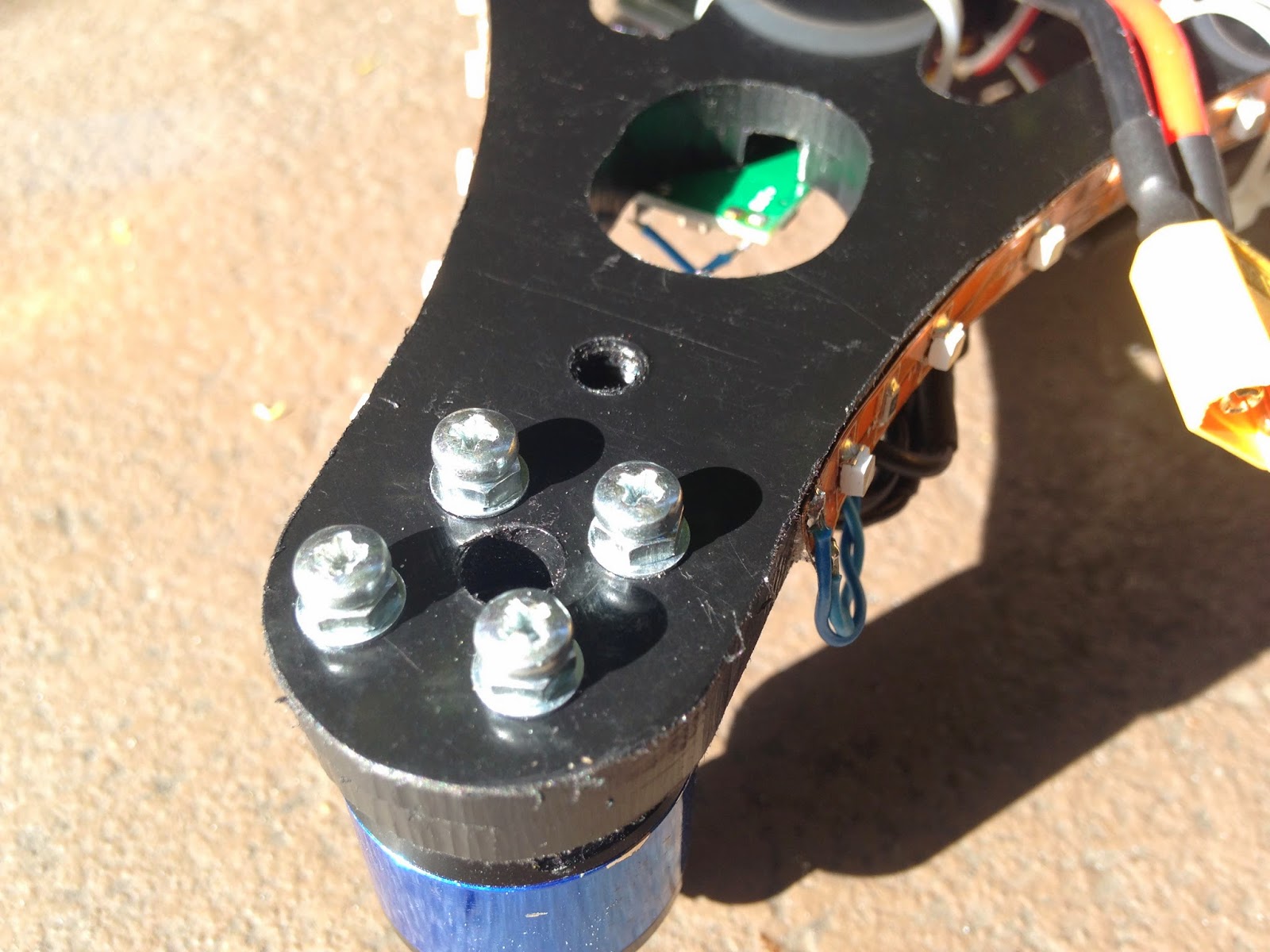
I made all the motor attachments using only two bolts per motor. It seems to make a nice sturdy connection. I used M3 x 10 bolts.
Start by attaching a motor to Arm 3. Note that Arm 3 is extending away from the gimbal. This was for convenience in experimentation, and I'll flip it around so that Arm 3 extends under the gimbal when I've got everything figured out.
Atach Arm 1 to the motor attached to Arm 3. This motor controls the roll by rotating Arm 3.
Put the ball bearing into the 8mm hole in Arm 2. I screwed up ordering my ball bearings from ebay. I ordered 3x8x4, when I should have ordered (I think!) 4x8x3. Note how it stands proud by 1mm. That's not a problem. I had to replace the M4x10 machine screw lower down with an M3x10.
Attach the other motor to arm 2. Make sure the wire points towards the rear. If you get it wrong, just remove the motor and flip 180 degrees.
Oops, before you attach the motor attach the M4x10 machine screw. It's easier to screw in if you do it before you attach the motor.
Here's what Arm 2 looks like when it's completed.
Be sure your ball bearing is in Arm 1, and wiggle Arm 2 into Arm 1. Attach the motor. Arm 2 should rotate smoothly in Arm 1.
I had to replace the M4x10 machine screw with an M3X10 machine screw in order to fit in the ball bearing. The extra mm of ball bearing width did not affect the fit. I had to be extra careful tightening the M3 machine screw to make sure it was centered, since the hole was sized for an M4 machine screw. So far it doesn't seem to have had a bad effect, but I'll get the proper sized ball bearing and swap things out if need be.
Here's the entire unit assembled and hooked up.
(photo question: all these pictures were taken by the same iphone. Is there a way I can force the white balance to be consistent?)
I'm not sure why, but the roll is super-unbalanced. I drilled a hole and screwed on some random pieces from the junk box to make it balance. It would be great to figure out how to eliminate these weights.
The sensor board fits nicely in the new revision of Arm 2. I attached it with two M2x8 machine screws and locknuts. I was concerned that there wasn't enough vibration protection because of the direct attachment, but I haven't noticed a problem yet. If I do notice excess vibration, I'll try using some gyro tape instead of the screws.
I drilled a hole on Arm 3 to attach a zip tie for strain relief. Move arms 1 and to into their farthest positions to see how much wire slack is necessary.
I downloaded and installed the latest BLG software for the Martinez board. Be sure and unclick the "reverse Z axis" option, since the sensor is sitting component-side-up. I'll follow up later with some notes on the latest BLG software.
Here's two videos showing the progress so far. I've done a bit of tuning. I think the tilt axis is good, but still need some work on the roll axis. I'll get the RC tilt/roll control going as well. More to come!
Well I finally got all my stuff together and put together my OPQ. I'm not wanting to boast (hmm actually I do!), but it is a genuine Crash Hancock Signature Edition!
The new OPQ models have nice mounting slots. This early model didn't, so I had to drill my own mounting holes.
It was easy enough, just clamp a motor mount onto the arm and use it as a drill guide.
I make a bit more clearance for the bottom of the motor.
Looks good! I understand why people enjoy working with delrin.
Here's the final mount. That motor's not going anywhere! Not shown: two of the arms were a bit off, so I just used two bolts. They still look rock solid.
It was handy to have some metric sized drill bits to get the exact size holes. I wish Amazon had better deals, or that HobbyKing or somebody would carry metric drill bit sets. I bought this set from a tiny shop in the Akihabara district of Tokyo that specialized in all kinds of electronics and small machine tools.
I screwed the power distribution board onto the top. It was nice and flat, so no problem to mount the flight control board on top.
Black on black with black trim looks cool, but might be a bit hard to see in the evening! Here's some lights.
The lights look good outside, but are a bit bright. I'm going to wire them to a brushless motor controller so I can adjust the light while flying.
Ethernet wire seems to be great for wiring LEDs.
I'm trying this 3M Dual Lock for attaching the battery. It's super-strong and has a nice clean "snap" when it connects. (update: way to strong, you have to give a King Kong yank to pull the battery off. But it's great otherwise... I'm going to try trimming the piece down so there's a smaller surface area and see if that's better. If so, I'll try it on some other air units.)
As soon as I get around to it, I'll shorten all wires to eliminate the clutter.
Flying with a Flip 1.5. Forcing myself to be a better pilot who doesn't rely on a bunch of sissy autopilot stuff!
Hot glue seems to work well for insulating the LED strips.
I tried this voltage converter for the dimmer, but the adjustment was pretty rough.
Part 2 coming up, it's a sweet flyer!
blogodex = {"toc":"The One Piece Quadicle","index":["opq","builds","Crash Hancock", "CrashCast","The Fleet"]};


 Now follow the endpoint syncronization procedure for your ESCs. Almost all of them are similar to the procedure in section VII of this manual.


 I drilled a hole on Arm 3 to attach a zip tie for strain relief. Move arms 1 and to into their farthest positions to see how much wire slack is necessary.