Tuesday, November 29, 2011

Getting started on Arduino: what to buy and where


Andreas asked me about getting an Arduino development board, and this is what I told him, based on about a year's worth of experience.

Uno

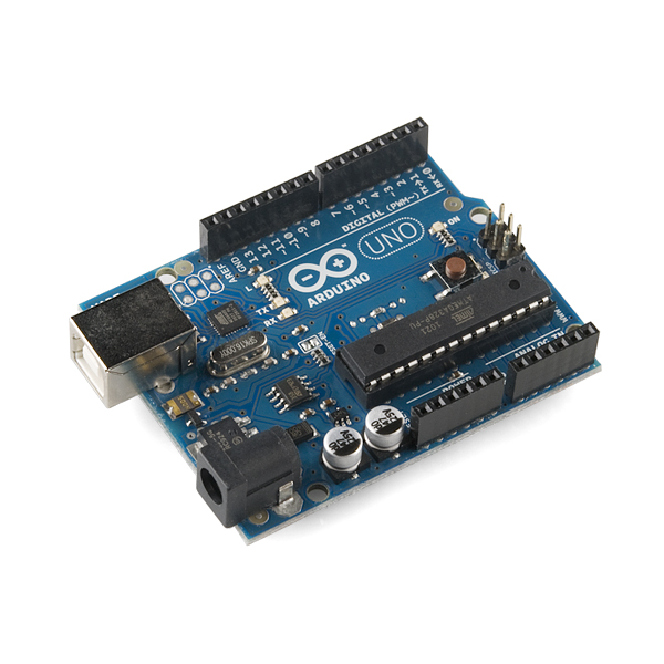
It seems the industry standard for standalone boards is the "Uno", which uses the ATmega328.  If you see a web page mentioning the Arduino Duemilanove, it's probably pre-dating the Uno.

    http://www.sparkfun.com/products/9950
    http://www.sparkfun.com/products/10356


I bought the Sparkfun Inventors Kit, which was a good way to get started. It has the Uno and pieces for various projects.

    http://www.sparkfun.com/products/10173

The best feature is this nice project book, which is worth checking out in any case.  It's a good introduction to the software as well as the hardware.

    http://www.sparkfun.com/tutorial/AIK/ARDX-EG-SPAR-PRINT-85-REV-10.pdf

Ardweeny

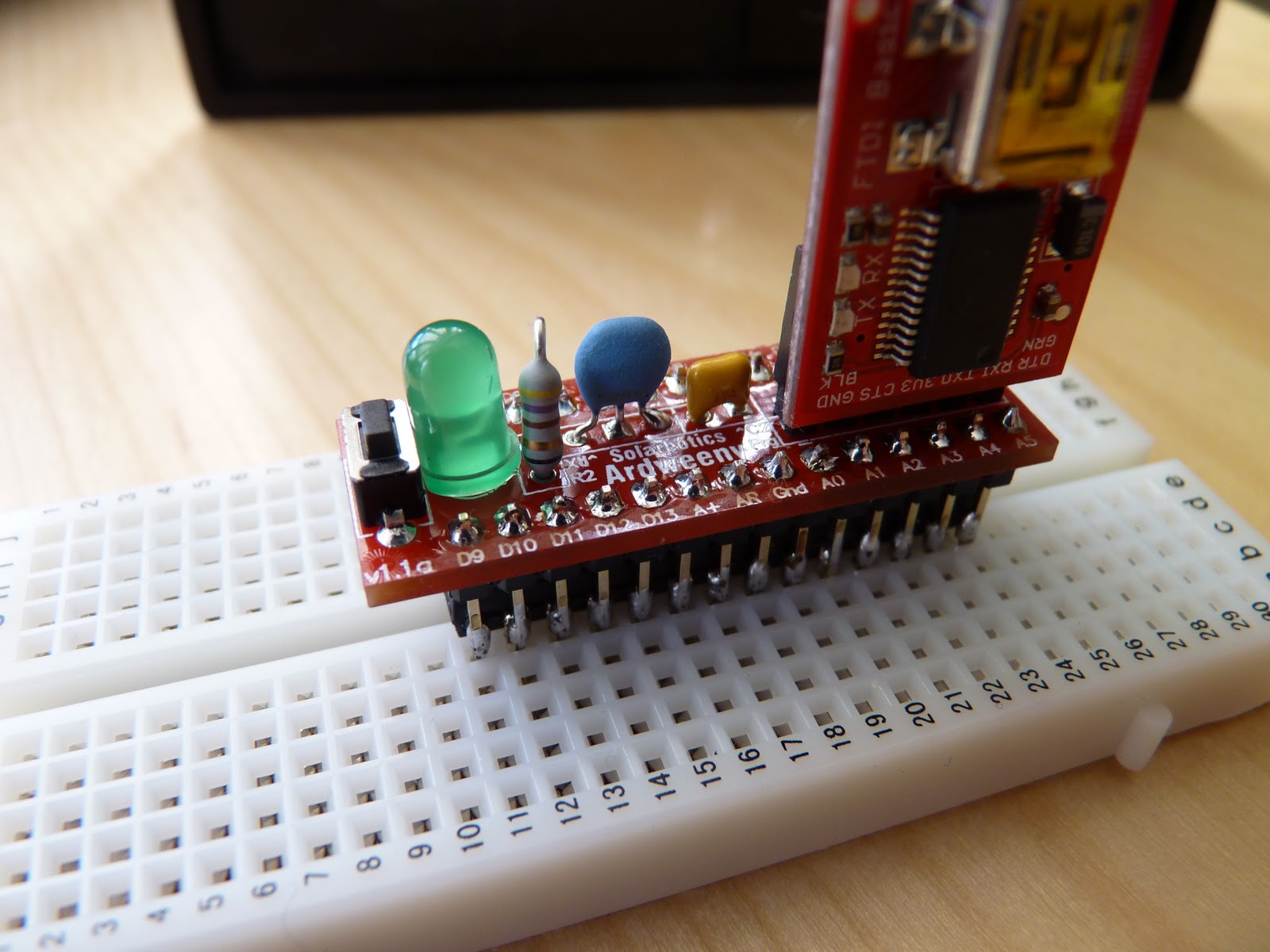
I got the Ardweeny too, which is a pretty neat little system, and awesome for $10.  For a lot of projects, an Ardweeny with a breadboard will do everything the Uno will do for 1/3 the price if you're comfortable with the soldering.  It was one of the first "real" projects I soldered and I didn't have any problems with it.


    http://solarbotics.com/products/kardw/
    http://eastbay-rc.blogspot.com/2011/11/ardweeny-tiny-little-arduino.html

FTDI Adapter

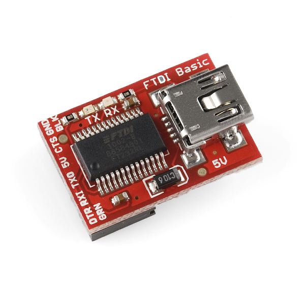
The Ardweeny needs an FTDI adapter, which plugs into a USB cable.  If you're messing around with other Arduino projects like the MultiWiiCopter you will probably have one already.  If you get an Uno, you just need a standard USB cable.

    http://www.solarbotics.com/products/50512/
    http://eastbay-rc.blogspot.com/2011/10/ftdi-and-avr-cables.html
    http://eastbay-rc.blogspot.com/2011/11/attaching-ftdi-connector-to-arduino.html


Clones

My friend and coworker Mark VandeWettering (also the proprietor of brainwagon.org, which you should be reading if you're interested in Arduino things), has mentioned that he's using the OSEPP Arduino clones from Fry's.

    search for OSEPP at Fry's

DealExtreme carries some clones as well.  Radio Shack is selling genuine Arduino products at about the same price as Sparkfun.  It's nice to see them getting back to their electronics tinkering roots.

ATmega2560

To get the ATmega2560, it seems the choice is pretty limited.  It seems that most people's projects fit in the ATMega328 space, so there's not the broad variety of boards in various configurations.  Or perhaps it's just a matter of time?  In either case, avoid the ATmega1280 unless the price difference is worth not having the extra 128K of memory.

    http://www.sparkfun.com/products/9949
    http://www.frys.com/product/6745685


Or, even buy one from diydrones.com!  I think the main downside of this one is that you have to solder the headers yourself.  But it could later be used with an Oilpan and have another complete Ardupilot Mega system.

    http://store.diydrones.com/product_p/br-ardupilot-01.htm


Bits and Pieces

For electronics pieces, Fry's or http://www.goldmine-elec.com.  Get the pieces outlined in the inventors kit above, or if you have a specific project in mind follow the instructions for that.  Get a few small breadboards.  Nothing kills your enthusiasm like having to disassemble and reassemble every project when you want to show somebody something.

My Recommendations

  • If you're an absolute beginner like I was, get the Inventor's Kit.
  • If you're comfortable soldering and want to save quite a few bucks, get one or two Arduweenys and some breadboards.
  • If you're familiar with electronics but don't want to solder, get an Uno.
  • If your project requires an ATmega chip, you don't have many options other than the ATMega2560.
  • Get some extra breadboards.  Goldmine has some cheap ones.
  • Get some extra parts -- resistors, LEDs, etc.

If I had to do it all over again, I think I would get an Ardweeny
and a couple of breadboards.  Then you can keep the wiring all together,
and move the Ardweeny between boards.  (plus random resistors, leds,
etc)

Maiden Flight, Andreas' Zephyr II

 Just got back from Andreas' RiteWing Zephyr II and wanted to get this uploaded as quickly as possible.  It arrived yesterday, he got it ready to fly in a day... send me a quick note to see if I wanted to run out and give it a try.  Yes I did, so off we went!
Even with a 5000 mAh battery, the inital flight seemed tail heavy.  We added in another battery as ballast, and also fiddled with the subtrim.  It looks like, as expected, it won't be a problem to load the thing down with FPV and autopilot equipment.

Launching turned out not to be as much of an issue as we feared.  When the prop is wound up it handles the weight of the plane, so the launching assistant just needs to keep it flat as it takes off.  Don't hold it by the conveniently located motor mount though, even when just carrying it around!

I took it for a small flight so Andreas could get a feel for the throwing.  It handled very nicely once it was trimmed out.  At half throttle it would hold its heading and altitude hands off.   You can see how smooth it is in the video when it comes in for a landing.  Chris Klick mentioned that one of his goals with the Zii was to make takeoffs and landings easier... I would say he succeeded admirably!

Here's some video of the maiden, taken with my iPhone at the lovely Berkeley Marina and rendered in genuine ShakyCam (tm).  There's a seagull that chases the thing around. Andreas interpreted it as agressively trying to chase the Zii away, but I think it's such a good looking wing that the bird fell in love instantly.  Can the Zii outrun a seagull?  The suspense will thrill you!


Monday, November 28, 2011

Ye Olde Workshoppe

A friend asked about my workshop, so I thought I would take some pictures and post.  It's in a corner of my basement.  A coworker gave me some nice florescent lights which I've put to good use here.  I hot-glued some foam on one end so as not to bang my head. Behind the big stack of all kinds of foam is a super-heavy vertical file.  I brought the nice glass-door cabinet back from China.  It was only $60!  We're not allowed to count the basement space in the square footage of the house because the ceiling is not 8' high, but it's still a nice work and storage space.

 Sometimes I worry that I'm going to end up on the hoarders TV show.  But at least my hoarding is OCD-level organized... I could be a crossover show!  I've scrounged these computer boxes from recycling; they make great shelf organizing units.  The shelves were from Target.  I got them on sale, three pieces for $99.  I've been trying to think of an excuse to get rid of them for the last 20 years, but it always seems easier to repair them than to replace them.  That's OK, I'm sure the replacements would be identical-looking ones from Ikea.
 Of course, I also have a full complement of plastic organizers.  I have some from Harbor Freight which are nice and tight, but with razor-sharp latches.  My favorites are from Ace.  As you can see, I have a label-maker and I'm not afraid to use it.
I could run a small hobby shop from my supply of electrical connectors.  About half of my first six months of messing around with RC planes was spent waiting for various connectors to arrive from China.  Apparently there's some kind of international regulation that no two pieces of RC equipment in the world should come with compatible connectors.  See the blog label connector-mania to enjoy the fruits of my many hours of research into electrical connectors and their names.


My workbench is the cheapie table from Ikea.  The legs were $20 for 4, and the top is $6.  I saw Crash Hancock had a nice glass tabletop to protect his workbench.  I thought about doing this until my wife pointed out that I could probably buy 20 tabletops for the same price.  One of the smartest things I did was buying a nice Weller soldering iron.  The tool holder thing is from a Harbor Freight tool case.  It's attached to the pier with a big zip-tie, the plastic industry's answer to duct tape.


Here's my view when sitting at the workbench.  On the wall is my French-themed Nutball.  It was supposed to be a patriotic USA design, but everybody that sees it thinks it's French. The bookcase holds the overflow from upstairs.  It's from Ikea too!  I didn't like how things were arranged, so I'm rearranging it one more time (see above comment regarding OCD!).

Saturday, November 26, 2011

NAPA autoparts power distribution

Vito on RCGroups noted this item for use as a power distribution connector:

I was looking around NAPA autoparts and saw this. The 16-14 gauge fits the RCTimer 30A controller and it has a center hole to solder the battery lead. Two per package - and it is riveted so no screw to loosen. I'm not sure if I will solder or crimp. 

Ardweeny -- tiny little Arduino

Here's the Ardweeny from Solarbotics.  It's an Arduino system based on Kimio Kosaka's One Chip Arduino.  I got it partly to have a small, cheap Arduino for breadboarding, and partly to practice soldering on a real project.  I'm going to use it to write some code to understand the AT interrupt driven timer.  It will conveniently hang off my laptop nicely without the size and weight of the Uno board, and provide a second processor type to force dealing with the hardware differences.

Here you can see that it's soldered to the top of the ATmega328P.  You can see one pin with much less solder than the others, but it's firmly connected to the chip.  I'm not sure which is better.  If you have an opinion let me know in the comments.
To program, you need an FTDI adapter.  Note that there's a tiny "-" on the board that lines up with the BLK connector.  The Ardweeny can be powered from the FTDI adapter.  It has a reset button and an LED on pin 13, so you can run a standalone blink program!


Here's a shot showing all seven (!!!) components and the pin names.  To program, choose Duemilanove/328 in the Arduino environment.  I'm really impressed with the parsimony of the design.  I think on a future page I'm going to go through each of the seven components as a learning exercise and document what each one does.  


Friday, November 25, 2011

Vibration Isolators, Industrial Strength

Helical Isolators.

"John Evans' helical isolators are made of aircraft quality stainless steel cable, wound into metal retaining bars prepared for surface mounting. The wire rope (ranging in diameter from 1/16" to 1"+) and its helix configuration provide the specific resilience required to cushion fragile loads as small as a few pounds or substantial loads of many thousands of pounds, and absorb vibration through a wide frequency spectrum. The isolator is essentially insensitive to position: it operates well in any attitude; in compression, extension, shear and roll, and provides protection in all axes simultaneously."

This is the method being used for the Flexacopter.

Vibration Isolators

It seems half the problem is knowing what something is called!

Vibration-Damping Grommets & Mounts


Thursday, November 24, 2011

KapteinKUK's flying VTOL bottle

The Kaptein says, "A single propeller VTOL thingy."  Includes source for KKBoard controls.


  • Servos: HXT900
  • Motor: DT-750
  • prop: GWS 12x6 slowflyer
  • batteries: 2 x 1.8Ah 3S
  • weight without batteries: 495g

"It is a quick hack of wood spatulas, zip ties, tape, CD control horns, hot glue, depron and one 1.5l plastic bottle."

Saturday, November 19, 2011

an Arduino sketch for transmitter tuning


One heachachy thing of dealing with quad is the need to plug the quad into the computer and run the quad tuning software in order to fiddle with your radio settings.  That wouldn't be so bad, except that I fanatically remove the props whenever I do this, which of course means you  then have to turn around and put them right back on.


So, I put together this quick Arduino project to read and display the PWM values from the receiver.  This has allowed me to spend a lot more time fiddling with the often inscrutable menus of the Turnigy 9x and making sense of them.


I made these connection wires to reduce the clutter of having six full three-wire servo connectors.  One end has a male connector and connects to the Arduino; the other end has a female pin and connects to the signal pin of the receiver.  The standard connector goes to an ESC and battery and provides power to the ESC.  I think the Arduino has enough power that it could be used instead.


From the Arduino environment, click the Terminal button and you'll see this output. Nothing fancy, but it allows accurate fiddling with transmitter controls.


This version of the code uses pulseIn(), which nicely does the right thing but suckily does it very slowly.  It's fine if you're just printing out the values, but if you were wanting to do some real control work in between reading the signals, it wouldn't work very well.

#include "WProgram.h"

#define NCHAN (sizeof(chan)/sizeof(chan[0]))
int chan[]={2,3,4,5,6};
int val[NCHAN];

void setup()
{
  int i;
  for (i = 0; i < NCHAN; ++i)
    pinMode(chan[i], INPUT);
  Serial.begin(115200);
}

void loop()
{
  int i;
  for (i = 0; i < NCHAN; ++i)
    val[i] = pulseIn(chan[i], HIGH);
 
  Serial.println();
  for (i = 0; i < NCHAN; ++i) {
    Serial.print(i+1);
    Serial.print(": ");
    Serial.print(val[i]);
    Serial.print("    ");
  }
  //delay(20);
}


Here's some code that uses interrupts to get the timings.  This would be useful on an Arduino Mega, which supports interrupts on six pins.  If you don't have a Mega, you've only got two pins so you're better off with the code above.  There are two other problems with  this code:
  • micros() returns a value which is rounded to a multiple of 4 microseconds, totally unacceptable for tuning radio PWM signals.
  • digitalRead() is very slow and can be made much faster.
I'm going to keep working on this approach, and I'll update later when I've got something to show.  I'm also thinking of making a GUI using Processing.

// reading a PWM signal using interrupts

int pin = 2;       // arduino pin number
int intrnum = 0;   // interrupt number, 0-5 for mega, 0-1 for others

volatile int width;  // width of most recent signal
volatile unsigned long start;  // start time of rising signal

// myisr -- interrupt handler
void myisr()  
{
  unsigned long now = micros();
  int val = digitalRead(2);     // are we high (meaning pulse just started)
                                // or low (meaning pulse just finished) ?
  
  if(val == HIGH) // ascending edge, just save off start time
    start = now;
  else // val == LOW, descending edge, compute pulse width 
   width= now - start;
}  

void setup()  
{  
  Serial.begin(115200);  
  pinMode(pin,INPUT);  
  attachInterrupt(intrnum, myisr, CHANGE); 
}  

void loop()  
{  
  Serial.println(width);
  delay(10);  
}

Thursday, November 17, 2011

Attaching an FTDI connector to an Arduino

 Here's how to hook up an FDTI connector to an Aduino card.  You need one of these when you're programming an Aduino that doesn't have a USB connector.  In this case, it's an Aduino Mini mounted on a MultiWii Paris board.

The FTDI connector plugs into the six pins on the top of the card. You don't need to care about the pin names, but note the BLK and GRN labels.


 Plug a mini USB cable (technically a "USB 2.0 Mini Type B 5 position")  onto the FTDI card and attach it to your computer.  Your computer should load the correct driver.

The FTDI connector is not keyed, so it's easy to attach it backwards.  Nothing bad will happen, but it won't work. There are BLK and GRN labels here as well.  Line up the labels with the Arduino and make the six pins are going into the six sockets.


Your software will have some menu for picking the serial port and baud rate.  On my windows box it's COM6, and on my Mac it's some odd name with "USB" in the middle.

BTW, I don't know what BLK and GRN stand for.  I'm assuming it's "black" and "green", and that some ancient connector used wires of those colors.  In any case, all modern FTDI connectors are cards, and they're all labelled with BLK and GRN.

A Handy Sticker for my Charger

Here's a handy sticker showing all the important charge values for 1-4 cells: low (absolute and recommended), nominal, and high.  I should add a row for LiFeP04 batteries.

Sunday, November 13, 2011

Thera-Band Prop Saver bands

 I was looking for better prop saver bands and heard someone mention "Thera-Band" exercise bands as an option.  I bought a couple of feet of "Blue extra heavy Theraband" on ebay from vendor drdcsupplies.  It cost $1.45/ft postpaid (not $1.80 as I mentioned in the video) and arrived quickly.
 I cut some 1/8 inch lengths with a side cutter.  I tried using regular scissors but had a problem with the tubing deforming and not quite cutting straight.

They fit nicely on the prop saver, held tightly and smoothly, and showed no signs of distress when stretched.
Here's the rubber bands from summer.  They worked fine when I first put them on, but rapidly developed cracks.


Here's a video:


Friday, November 11, 2011

Arcticopter IV power loading

    battery  amps watts     notes
3S 2200 15c    .5     6     powered on, no props
              3.2    36     armed, motors at lowest speed
             16.0   184     half throttle
             33.3   313     full throttle (15c)
3S 2200 40c  39.3   413     full throttle (40c)


motors: hacker Style Brushless Outrunner 20-22L x 4
ESC:    Turnigy Plush 18A x 4
props:  10x (3.8?? 4.7?? I will check later...)


Wednesday, November 9, 2011

HobbyKing KKBoard Notes

For $25, I couldn't resist getting one of the Hobby King V2 KKBoards. The minimalist elegance of  3 gyros, 3 pots,  and 4K of AVR Assembler speaks to me! KapteinKuk is one of my favorite RC people!


Programming Instructions

Dadde87 has everything here.  Note that his programmer connection diagram is mirrored from how a lot of people think about the connectors.  I've written down my connector interface below.


Programmer

Using this USBASP AVR Programmer purchased from EBay seller egochina8848 designed by fischl.de. It's usbasp in KKFlashTool.

      (BUMP on top)
MOSI NC   RST  SCK  MISO    <-- looking at pins
VCC  GND  GND  GND  GND


KKFlashTool

Flash Tool is here.  Be sure and flash the "1 Sec Clock Test" and see if the LED blinks once per second to ensure you're AVR programmer is working properly.


My Connector

I took two servo wires and cut one end off, leaving the female plugs.  I attached male servo pins to each of the wires on the other end and covered them with 1.5mm shrink tube.  You can do the same thing with a servo extension wire.  I attached the servo plugs to the six pins of the board (white wires towards the motor pins, and with the right plug labelled), and inserted the individual pins into the programmer as per the notes above.  Once I tested the unit I put a piece of 7mm shrink wrap around the wires near the single male connectors to help keep them in the holes.


Monday, November 7, 2011

MultiWii Camera Test

So, I've been wanting to try out the camera stabilzation features on the MultiWii controller, and prompted by an interesting camera stabilization link from my friend Craig I went ahead and put a quick prototype together.  I had been waiting to put together something like this nice gimbal;  I'll get to that soon, but in the mean time here's what I did with hot glue and spare parts sitting around.  There will be lots of jitter with this design, but we'll see if the roll and pitch adjustments are close.
I started by configuring the MultiWii software (notes below) and enabling stabilization in MultiWiiConf.  To hold the camera, I noticed that the Radical RC quad motor mount was the perfect size to hold a GoPro.  By using a clamp while CA'ing the joints (careful not to drip!) I was able to get enough of an angle so that the camera fit snugly enough so that for testing I didn't have to use any other mechanism to hold the camera.
I used two 9 gram servos to make a two-axis gimbal.  Note that this isn't the final plan, but for quick prototyping it's hard to beat, taking about 15 minutes to assemble everything after 30 minutes of fiddling with various parts trying to figure out what fit best where.
I sandwiched one servo between two Radical RC boom mounts and fixed it into position with hot glue.  Put the mounts on the boom and it will be easy to align.  Be sure and use the high temperature setting on your glue gun or the plastic servo body won't stick very well.  Attach the cross-shaped servo arm for maximum surface area to attach the second servo.  Don't forget the screw!
Remove any labels and then hot-glue the second servo onto the  servo arm.  It should be perpendicular.  If you get it wrong, you can clean up the glue joint with rubbing alcohol and try again.
Finally, attach a cross-shaped servo arm to the second servo and hot glue it to the camera mount.  Be sure and check your alignment; my first attempt was very crooked and I had to redo it.
Here's what the mount looks like when it's attached to the rear mounting arm of Arcticopter IV.  I put it in the back so that the Arcticopter arms would appear in any test videos to show the real motion of the unit.


Here's a couple of videos showing the result.  The first one is an overview.  The second is from the GoPro pointing at my iPhone, and the third is from my iPhone pointing back at the GoPro.

Overall I'm pretty pleased with the results.  Ignoring the jitter resulting from the horizontal extension, the camera stays remarkably still.  I need to adjust the rates a little in the software, but it's pretty close as it is.  I had expected the most jitter when pitching down (resulting in the camera moving up); I was a bit surprised that the major jitter was the opposite... the servo would attempt to move the camera downward, gravity would pull the camera down, causing the servo to push back up.  Repeating this through the pitch movement set up an oscillation that really forced the jitter.

Although I must say that if the Arcticopter were moving around like this in flight and if I were the pilot, the last thing to be concerned about would be camera jitter!

Overview video:

Making sure the gimbal motion would clear the mechanism:

Stabilized view from the GoPro, with appropriate jitter disclaimers:

Another view, from the workbench:

Configuration Notes.  If one of the servos is going backwards to how it should be, make the TILT parameter negative.


MultiWii_1_8_patch2 $ diff config.h-orig config.h
66c66
< //#define SERVO_TILT
---
> #define SERVO_TILT
74c74
< #define TILT_ROLL_PROP    10
---
> #define TILT_ROLL_PROP    -10
103c103
< //#define BMA180
---
> #define BMA180

In MultiWiiConf, enable camera stabilization in all modes.


Crazy-J's rather nifty GoPro gimbal

This gimbal is what I'd like to make.  Like everything he does, it reeks of awesomeness!

http://www.bayrc.com/boards/viewtopic.php?f=50&t=8380


"It is using a HXT 9gram servo for pitch, and a HS85MG for roll. Essentially, I built a basswood cradle that fits the GoPro snug and then created a pivoting system around it. The cradle is reinforced with .5oz fiberglass cloth and thin CA. There are two Dubro 4-40 ball links that screw into 4-40 blind nuts installed in the cradle. The 4-40 ball links are the pivoting point for the pitch axis. I don't get a whole lot of pitch movement, but that can be changed easily if I want to. The whole system without the camera weights less than 3oz (just a guess, it might be less!)."
Update: here's the new gimbal from diydrones.