Friday, March 30, 2012

Turnigy Micro-Quad build, part 1

 I'd been looking for a small quad kit for a while... something that I could fly inside the house without making it sound like we were under attack.  When HobbyKing announced their micro-quad I thought I would give it a go.

It arrived very nicely packaged.
 And inside the package, everything very tidily laid out.  Fiberglass body parts, and an integrated power distribution setup.  More on this below.
 Parts List:


Update: Now there's a receiver-ready prebuilt ARF which includes a KK2 board.


Ikea-style instructions!

 Here's the power distribution part of the board.  The power side of the ESCs are soldered directly onto the PCB pads, and there's a spot for a JST connector to be soldered.
 The flip side (which is the top) has the four wires necessary to interconnect the positive and negative poles.
 The laser cut fiberglass turned out to be really easy to disassemble.  Wiggle the pieces a bit and they will twist loose with no problem.  I used a pair of small pliers to snap off the little connector pieces.


 Here's the power train, minus batteries.  Hobbyking sales hint if you're in the US:  If the batteries you need are so stocked, order them  separately, and get them from the USA warehouse.  This will speed up your order shipping from the International warehouse since there won't be any LiPos that will cause slow shipping.
Here's one set of everything.  Vendors must love multicopters, since they sell 4x or more of all the components!

I had planned on using the nice-looking spinners that came with the motors, but the props didn't fit.  I didn't want to spend time hollowing out the props so I'll use the included prop savers instead.  You won't need the included bullet connectors or shrink tubes.
 Here's my KK board, installed on my East Bay Standard control board carriage.  We won't need the carriage for this tiny unit!
 The King was out of stock on the M2x8 bolts and M2 lock nuts.  That's a shame, coz buying them locally cost an arm and a leg:  36 and 28 cents each, respectively... ouch!!  I tried fitting some cheaper imperial screws, but couldn't find any that were noticably cheaper that fit to acceptable tolerance.


 Snapping off the retaining pieces as noted above.
 Here's the frame dry-fitted together.   It holds together pretty nicely, so you can put off gluing the pieces together until after all the other construction steps.


 Here's the top shield.
 The holders were a bit wiggly.  After they're screwed onto the board it's pretty secure.
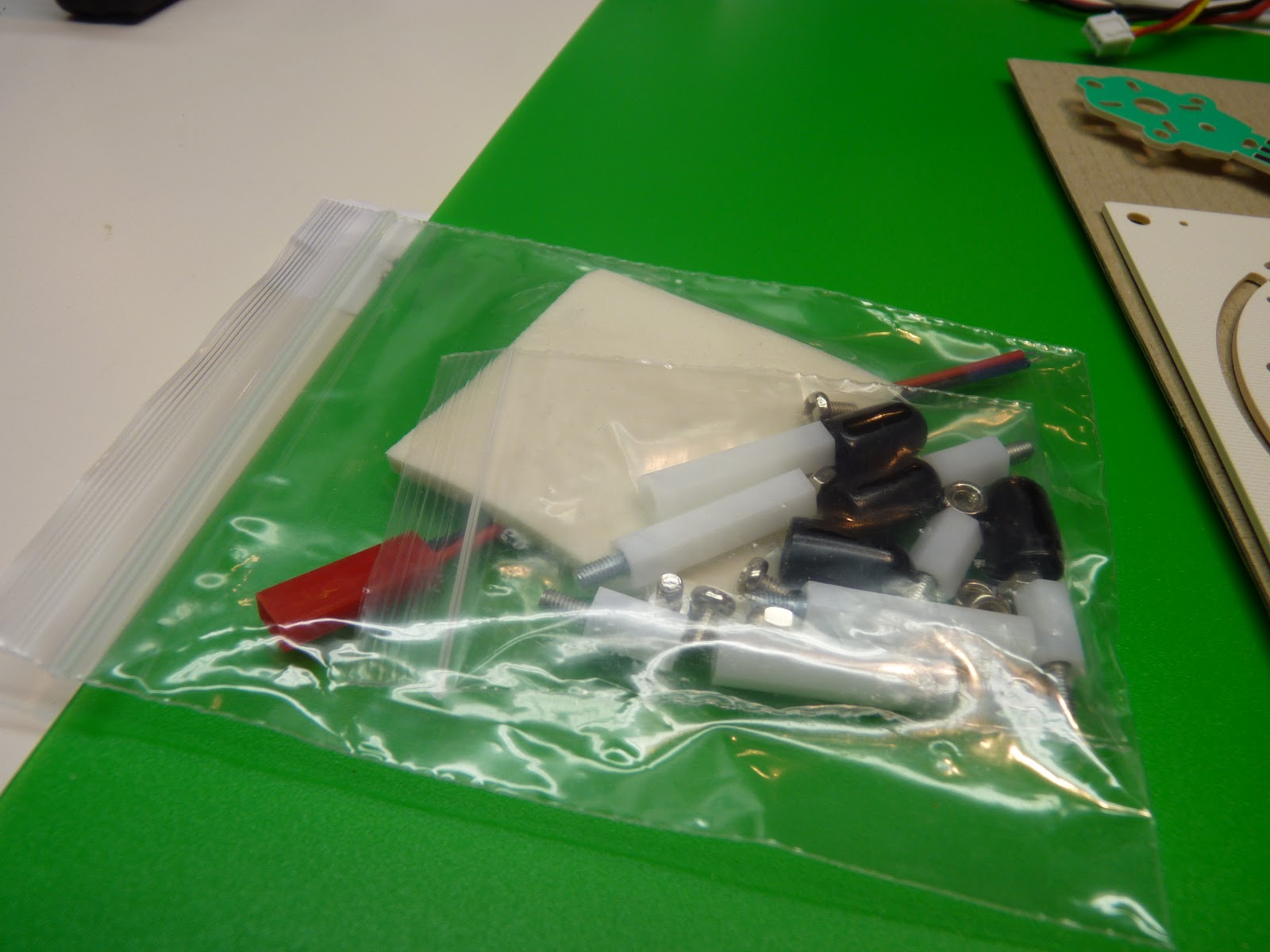
 Here's the included hardware.  It's everything needed except for the motor mount.
 Everything dry fitted together, with the top bolted on.
 Here's the leg mounts, assembled and ready to attach.
 The shield bolts seem a bit short.
 Everything attached, looking from the top.
The fully assembled frame, bolted but not glued.
 The motors, motor mounts, and spinners (which won't be used -- see the next step).

(UPDATE: ignore prop information below.  see part 2 where I recommend using a hammer to pound the props on.)

 Here's the prop... notice the tiny hole.  Let's try the prop saver!
 You will need a 1mm hex wrench to install the prop saver.  Put the big rounded end out.
 The motor includes an o-ring to attach the prop.  I've had much better luck with theraband prop savers.
The small prop hole doesn't fit onto the end of the prop saver, but if you wiggle the prop a bit it will fit snugly on the end.  Don't forget to balance the blades.


To be continued...

Thursday, March 29, 2012

Post #500!

While fiddling around with the blog settings this evening I noticed that I had 499 posts to this blog.  What a great opportunity to post this quick message and have it come out as number 500.

Thanks to all those who have helped me out from those days when I was trying to figure out which end of the plane to throw in the air first.  I really appreciate it, and am happy to have heard from so many people who have told me that they've benefitted from something I've written.  Remember, it's just an ongoing journal of my own ignorance!

This blog's first post was on July 1, 2010 and had some links to those crazy Utah electric combat fliers.  I still want to travel there and fly with those guys!


Friday, March 23, 2012

FrSky Voltage Monitor, with OLED screen

Well this is rather nifty... a voltage montor that shows 1-6 cells on an OLED!  It's from FrSky and designed to be part of their telemetry system, but works fine on the ground as a voltage meter.  Not bad for less than $12... I had no idea OLEDs were so cheap!

FrSky 1-6 cell voltage monitor

Thursday, March 22, 2012

Prop Slot noise reduction

RCG thread showing how to reduce prop noise by shaping a curve in the slot.  Otto Diefenbach includes some nice video demos.

Basic idea: the center is cut very close, and the edges slope away.

Monday, March 19, 2012

Sunny Screen Update

Sunny day today, so I could do a quick test of the sunny screen cutout.  Here it is with sun shining on the right part of the screen, and the left part of the screen shaded.  So far, it looks like it may work!  I'll try modding the second laptop that runs the APM ground station software.


Here's what the back side looks like.  I've got it taped up, but I'll put a piece of clear plexiglass or somesuch on the final version.

Sunday, March 18, 2012

APM: the East Bay Standard Configuration

Here's how I've got my Turnigy 9x / Ardupilot Mega configuration set up.  I'm going to call it the "East Bay" configuration.

If you use this configuration and want a sticker drop me a line and I'll send you one!

9x Setup

(put link here)

Ardupilot Setup


    manual      rtl
    stabilized  auto
    fbwa        loiter

Arducopter Setup

(double check)

Video TX/RX fiddling

I think I've got just about everything needed for putting together the video Tx/Rx.  I've got both 1280 and 5.8 and will give them both a try.

I'll try all the various combinations of hooking things up, including direct connections from the cameras to the screen.  I imagine there will be much connectoring involved.

The diagram has all 8 possible connections among all the components.  I'll update as I get each one going.

FrSky installed, 9x module rejiggered

 Here's my FrSky module.  HK was out of the new model with telemetry, so I got the older model from Range Video.  Once the original 9x module was removed (more on that below), it was a simple matter to plug in the transmitter module and bind to the two receivers.
 I got the patch panel as well.
 Here's how the patch panel looks when installed.  I'll experiment with the range, it may be necessary to hold the transmitter a bit higher than usual?
 Here's what the transmitter module looks like from the side.  Very nicely, the  antenna mount points forward and there's a flat surface for the receiver to rest on.
 Here's my rejiggered 9x module.  I should have taken some pics of the disassembly, but it's pretty straightforward.  Open the Rx case and loosen the screw that holds the antenna.  Open the module and remove the board.  Unsolder the antenna from the board, and remove the antenna and wire.  Don't bend or break the wire, it's actually a coax cable soldered onto two pads on the board.  Once the 9x module has been removed, you're good to use the FrSky module.
 I drilled a hole for the coax and ran the antenna through.  I epoxied the antenna over the hole, scoring the module cover and drilling some extra holes around the base for the epoxy to hold onto.

Here's an alternate method for removing the antenna that doesn't involve unsoldering and resoldering the connection.

 Resoldering the antenna cable needs a bit of care.  The two parts of the coax cable need to be soldered onto the two pads of the circuit board.  Study the board carefully before unsoldering and you'll see what needs to be done.

It turned out to be a lot easier than I thought it would be.  I didn't have to add any more solder or flux.  Hot glue the board into place as it was.
Here's what it looks like from the bottom.  Not quite as well as nice as the flat bottom of the FrSky module, but it doesn't seem to be too bad.  I'll point the antenna straight down when flying.

Thursday, March 15, 2012

Step Down PSU, 3.3v, 5v, 9v, 12v

Ordered this from hobbyic.com and stashing the docs, such as they are, here.  They note: "Do not power 1W video transmitter"

Wednesday, March 14, 2012

Zephyr II glued up!

Got the body glued up... wasn't quite sure what I was doing with the 3M 90, but it went not too badly.  That stuff is sticky.  I got some on my hand and had to wait for the next day for it to wear off.
I didn't get good coverage on the tips, but a bit of epoxy seems to have set things right.
I followed Chris' video for the motor mount installation.  It worked well.  I used a skinny hacksaw blade, so the motor mount was a bit of a tight fit and caused some cracking of the foam.  A bit of epoxy set things right.  Next time, I'll use a fatter blade, or make extra passes with the skinny blade to hollow the slot out a bit more.

Outdoor Screen Mod -- prototype

I heard Tridge mention in a presentation that they had solved their outdoor PC screen viewing problem by removing the back of their laptop.  I couldn't find any other references on the internet to this kind of procedure, so I thought I would give it a try and report on how it went.

tl;dr:  seems to work well, waiting for a sunny day to take it out and try it.

This laptop has a non-functioning battery and not enough memory to run the ground station, but seemed to be a good candidate for an outdoor viewing enhancement.  The basic idea is to cut the back off, and let the sunlight enhance the LCD backlight.  It was pretty straightforward on this Dell.  Pop the rubber caps off the bezel and remove the screws.  Jiggle the bezel and it will come loose.  Remove the screws holding the screen in.  They are all perpendicular to the screen.  There are some side-screws that hold the mount onto the screen itself, but you don't need to loosen them.  Once everything is off, you can fold the LCD down and away from the back panel.  Cover everything with blue tape and saran wrap.  I used a dremel with a large cutting wheel to cut a rectangle out of the back panel.  Be careful not to let the metal dust get into the laptop.  Reattach the LCD and the bezel.  Later I'll epoxy a plexiglass panel to the back -- now I've just got it covered in tape.


Here's a picture of the back when the laptop is powered on.  You can see the control wires, etc.


Here's a front view.  It seems a bit darker than usual (because it's not getting reflected light?), but still quite good, especially for an older model laptop.
Waiting for the rain to go away for testing, but holding the laptop up to an incandescent light makes everything brighter.  You can see the control wires shading the display.

More later, including a walkthrough, but for now this looks promising.

Saturday, March 10, 2012

Zephyr II bay measurements

I didn't see these online anywhere, so I made a few quick measurements, close to at least a couple of mm.  If there's more than one depth measurement it's front/middle/back.

            length  width  depth
    front bay  152    110  35-40-38
    back bay    70    110  20-15
    servo       53     40  20


Multiplatform XBee Configurator


The most direct way to configure simple parameters on an XBee is to use the "AT" command set.  For more advance things, you have typically needed to download the XBee configuration tool, which inconveniently in some cases runs on Windows only.  Moltosenso is multiplatform tool that might be useful.  The base edition is free; features like scripting are available in the premium packages.

Moltosenso's description from their web page:

moltosenso Network Manager™ IRON is the cross-platform answer for the users of Digi International® X-CTU™. The same functionalities are now available on Microsoft Windows®, Linux® and Mac OS X™ operating systems.

Thanks to a snappy and totally free GUI, moltosenso Network Manager™ IRON is able to grant:

  • get/set of the parameters of Digi International® modules plugged to the PC, both in API and AT mode;
  • get/set of the parameters of Digi International® modules remotely addressable;
  • an effective graphic test for RSSI parameter, especially tailored for XBEE™ modules;
  • firmware upload (local and - where available - remote) for many supported Digi International® modules.

eCalc propCalc -- Propeller Calculator!

Courtesy of the most awesome brosius85, here's a great power system calculator that seems pretty comprehensive.  It has a large selection of motor data, nice charts showing the power curve, and warnings when some parameter is out of whack.  Thanks Brosius!!

Wednesday, March 7, 2012

Notes for KapteinKUK PI Tuning Guide


How to recognize different gain settings.

Too low P-gain: @0:01
- hard to control
- easy to over correct

Correct P-gain: @0:45
- easy to control and fly

Too high P-gain: @1:22
- oscillates rapidly
- gains height easily
- hard to control height
- oscillating sound from the motors

Too high I-gain: @1:49
- same as with too high P-gain, but oscillates with a lower frequency

Single axis tuning on a string @2:08

Setup: @2:08
- set yaw PI-gain to zero
- set Roll/Pitch I-gain to zero

P-gain too low: @ 2:19
- slow and imprecise stick response
- easy to turn by hand

Increased P-gain: @3:09
- sharper stick response
- harder to turn by hand

Good P-gain: @4:08
- sharp stick response
- slight oscillations when releasing the stick
- hard to turn by hand

Too high P-gain: @5:05
- scillates rapidly
- oscillating sound from the motors

Good P-gain, too low I-gain: @5:38
- moves back to center when stick is releaseddue to gravity
- easy to move by hand over long time

Good P-gain, good I-gain: @6:17
- stays in position when stick is released
- very hard to move by hand over long time

Good P-gain, too high I-gain: @6:57
- oscillates, but with a lower frequency than with a too high P-gain

Monday, March 5, 2012

A nice UAV radio transmitter

Here's a controller for a huge moving truck, as seen on a clip from Extreme Machines.  I'd like to have something like this (not quite so meaty of course!) for controlling a drone.

In particular, the Arducopter software has a lot of variations (e.g. simple compass control) that would be nice to map onto a clearly-labelled, easy-to-hit button.

Are there any RC transmitters that feature a row of buttons or switches like this?  If so, I'd be interested in hearing about it!

Friday, March 2, 2012

New Superfly!

 Put the new Superfly together... it has the 5 inch center section.  Will try to maiden it tomorrow.
Saw a note from somebody on rcgroups, mentioning that they had attached the canopy with velcro.  I'm going to give it a try.

More later!

Thursday, March 1, 2012

Kicking off the Zephyr II build!

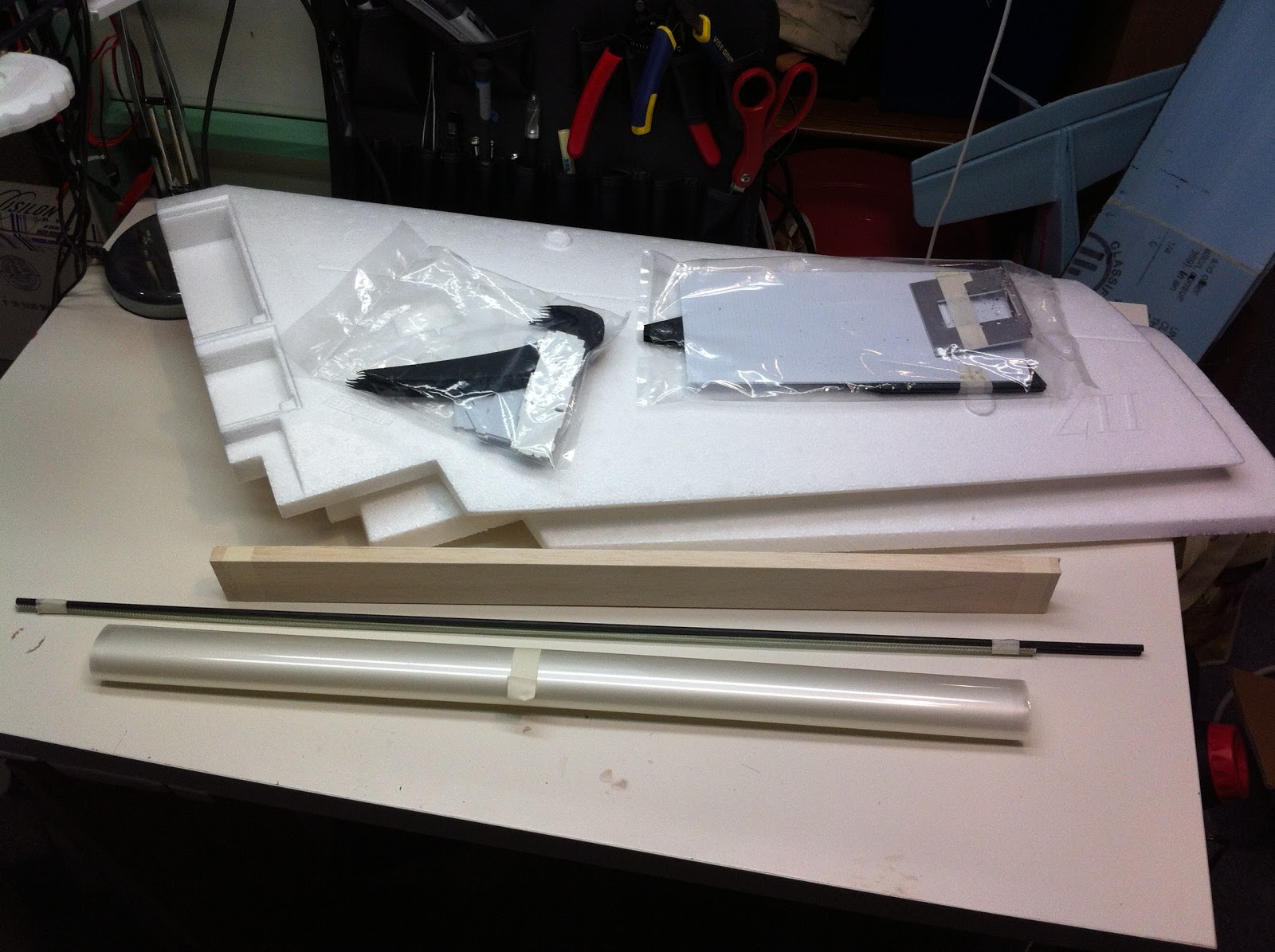
 Well it looks like our favorite uncle in Hong Kong is ALMOST ready to send a gift to me, so it's about time to get my Zii build kicked off.  Here's a couple of pictures of the Zii kit out of the box.  Andreas loaned me his can of 3M 90 spray adhesive, and I picked up a can of flat black spray paint.  Here's everything as they came out of the box.  The wings were wrapped in foamy wrap.
 Here's the (optional) gopro kit and skids come in one bag.
 The motor mount, battery compartment cover, and wing tips come in another bag.  There's a bit of cutting dust from the wing tips, so it seems like they're CNC milled?  Chris has a nice video about attaching the motor mount that you should watch before starting to build.
Left to right, the (optional) covering, spars (2 black, 4 white), and balsa ailerons.

Sunday, February 26, 2012

Sky Stick -- what to do with your Busted Hawk Sky

When it's crashes its final crash, what can you do with a smashed Hawk Sky? Turn it into a stick of course!


Saturday, February 25, 2012

Art of Electronics book

Here's where I got my copy.

Open Source Lipo Charger

Very Nifty! Paul Asselin has an open source hardware design, based on the Microchip MCP73831.  You can download the schematics and Eagle files directly. He also sells a kit or completed unit.

Sony 600TVL Super HAD board camera for FPV

As recommended by Bruce, who notes "I am not sure which lens I have on this camera -- I requested a 3.6mm lens but the box says 2.8mm. I will check and update the review accordingly."


BidProduct Crimping Tools

Will any of these work for balance plugs?  Must investigate!  Many more on the page.  PS, this is the site with all the micro receivers as well.

Zephyr II launching notes

From Chris:


Launch with 3/4 throttle to full power.
Align elevons to match wing top foil contour out by the wing ends
and give 3 to 5 clicks of up.  If you align with bottom you will
stall it as soon as you launch and naturally try grab for elevator
up.This will also cause the roll out during the tip stall, its not
an issue with lateral balance , its you stalling it by too much up
input and no airspeed.
Once you get it flying and trimmed power on then do a few passes
under good power and chop the throttle to see if she rises or drops
once power is removed.  If it does either than your thrust angle
is off ,and will need to adjustment.
Launching it with no power and holding it back by the prop opening
is just asking for finger slicing issues.