
Wednesday, October 12, 2011
Xoar Props -- big and wooden


Nice airbrushing
Tuesday, October 11, 2011
FTDI and AVR cables
Here's a quick brain dump of the differences between FTDI and AVR programming cables.


- Arduino things use the FTDI adapter. FTDI is basically a serial/usb converter.
- FTDI is a company, their main product is a serial/usb chip.
- The Arduino boot loader has code to handle the ftdi loading process.
- Shown is the Solarbotics FTDI basic breakout.
- The KK Board is more hard-core, non-arduino, "pure" atmel.
- AVR programmer is used to "flash" the on-board chip memory, like writing an eprom.
- If you want to take an atmel chip and make it into an arduino chip, you would use an AVR programmer and flash the arduino boot loader.
- Likewise, you use an AVR programmer to flash the kkboard software onto the atmel chip.
- Daddy87 has a great tutorial here.
- "Name brand" AVR programmers are, ironically, more expensive than the HK KKboard .
- But, lots of cheap vendors on ebay, all based on the open-source hardware design of Thomas Fischl: http://www.fischl.de/usbasp
- This one is from ProtoStack.
Sunday, October 9, 2011
cheap lightweight battery for Night Vapor

Of course, a lot of this is due to its light weight. 17g AUW with the supplied 70 mAh battery. Unfortunately, extras of this battery are $5.50 + shipping, and when I originally ordered I think it was closer to $8.00! So of course, everybody buys the cheaper, larger batteries.

So, when I noticed that Hobby King had cheap single battery cells, I thought I would try to make my own.

- Zippy 70 mAh, 20C cell. I bought 3 units to experiment with.
- Mini plug extension wire. Cut in half to use the female plug.
- 2mm shrink tubing. This is good cheap stuff to fill out the weight on any HK orders.
Total cost for 3 batteries: $5.50, $1.82 each.

The battery tabs take standard solder. I snipped and tinned my wire, and then tinned the battery tab, leaving a proper sized blob to attach the wire.

On two of the cells I make a straight solder joint, so I had the shrink tube on the wire as I soldered it. Because of this, the wires were a bit longer than I liked... extra weight, and I was worried it might not fit in the plane very well.

I think I'll resolder the other two cells in the same way.
[update: solved the charger problem using the 1S extension wires from Hobby King.]
Mini Plug Extention for Micro Battery 10cm (5pcs/bag)

The completed battery is too fat to to fit nicely in the holder, but a bit of blue tape holds in on nicely. I might a a tiny bit of velcro as well. When I flew it for testing, there was a bit more tape than what I'm showing here.

I didn't test relative flight times, coz I was pushing the testing between a couple of other activities. I'm guessing it will be comparable to the original battery, but I'll try it later and update this post.
I've misplaced my little subgram scale, but using my big scale show the following weights:
- Turnigy 138, 5g
- Parkzone 150, 4g
- Original Parkzone 70, 2g
- These replacements, 2g (I'm assuming the 3rd one was a bit less and would show it on the higher precision scale)
But, using my big scale, the the plane's AUW including the battery drops from 17g to 16g (with no battery, it's 14g). So, it seems that these replacements are lighter than the original, and could get even a bit lighter if I were more aggressive about trimming the wire.
They fit on the charger nicely... line them up and poke them in with your fingernail, pull them out by holding on to both wires (not the battery body) when finished. Note that I have to tip up the third battery to get it to fit into the solder. When I redo the others, I'll solder on the other side of the battery (if possible?) so that the batteries won't have to be tipped up; but it doesn't seem to be enough of a problem to resolder the one that's already made.
Update: Figured out how to eliminate the shrink wrap.
http://eastbay-rc.blogspot.com/2012/01/update-night-vapor-batteries.html
Update: Figured out how to eliminate the shrink wrap.
http://eastbay-rc.blogspot.com/2012/01/update-night-vapor-batteries.html
Turnigy 9x Trainer Mode
Here's some notes on setting up two Turnigy 9x radios in trainer mode. Thanks to Miki for asking about this and training new RC pilots!
I'll type in a few quick notes now; I'll try to borrow my friend's 9x, take some pictures and maybe a video of trainer mode in action.
Overview

I'll type in a few quick notes now; I'll try to borrow my friend's 9x, take some pictures and maybe a video of trainer mode in action.
Overview
- We'll use "teacher" and "student" here; The other common terms for this are "master" and "slave".
- The teacher radio is in contact with the plane.
- The two radios are attached with a 1/8 inch mono male-male jack. Student radio turns on automatically when attached.
Student Radio

- In new model 9x's (the ones with a single antenna), there is a circuitry problem that blocks the trainer port.
- The simple way to fix this problem is to pop the module out. The antenna connection is soldered to the main board, so be a little bit careful. You have 2-3 cm of loose antenna wire.
- With the module disconnected, the trainer port is active. I think it's ok to operate in this mode, just tape the module so it doesn't fall out and break the antenna wire.
- Another solution, but more work, is to solder a resistor into the circuit. I have not tried this yet, but have my notes on this page.
Teacher Radio
- Turn on trainer channels [menu / func setting / trainer].
- You can turn on all controls or just some. It might be useful for teacher to keep control of the throttle, for example.
- The settings are confusing. I will probably make a video, but I think you want to set Off/On mode. When in that menu, pull the trainer switch and you should see the mode switch.
- In most radios, you pull the trainer switch to allow student control, and let go of trainer switch for teacher to control.
- Turnigy 9x is opposite! Must hold trainer switch for teacher to control. Use this method for mechanical reverse.
Simple Summary
- Eject the module from student radio. Tape it down so it doesn't break antenna wire.
- Make sure "Reverse" has same settings on both radios. [menu/func setting/reverse].
- Set trainer mode on teacher radio.
- Attach mono cable to both radios.
- Test all controls to see if reverse is correct on both radios.
- Fly!
Saturday, October 8, 2011
Quad Dome from Electronic Goldmine

Green See-Thru Super Quality Acrylic Dome-The Electronic Goldmine:
"These domes make great additions to small robots. They are large enough to mount sensors, small circuit boards, LEDs, lamps, etc. underneath. Each dome is 2.83" in Dia. plus a .5" mounting lip. The highest part of the dome (at the center) is about 1" tall. These were made for large projection TVs and came in to us in sealed master cartons so they are in perfect condition. Green See-Thru.
Nice rule of thumb for COG testing
mikeruth @ rcgroups:
A general rule of thumb is on a calm day fly the plane upright and trim it out for straight and level flight at a moderate speed.
Then roll over inverted and see if you need to put down stick input in and how much. This is the tell tale sign of your CG.
3d planes typically will roll over and fly with no input and or climb becuase of the reward CG settings we like for 3D flying.
As you move the battery back, it's going to take less input or in my case require holding some up-stick just to stay level since I like a very tail heavy setup.
Friday, October 7, 2011
Wireless Simulator/Trainer Port - update
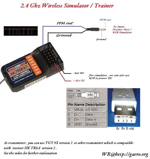
Well here it is:
http://www.hobbyking.com/hobbyking/forum/forum_posts.asp?TID=19313
Monday, October 3, 2011
XBee APM Overview

Sunday, October 2, 2011
Oddness in APM mission planner KML conversion?
version: APM Mission Planner 1.0.69
KML export seems to add some spurious locations pointing to an incorrect location.
If you look at the attached google earth screenshot, you can see there appears to be some spurious points in the data path. The points all go to my house, where I generated the file. Perhaps APM has set that as the new HOME location and some of the logfile points are relative to HOME?


KML export seems to add some spurious locations pointing to an incorrect location.
If you look at the attached google earth screenshot, you can see there appears to be some spurious points in the data path. The points all go to my house, where I generated the file. Perhaps APM has set that as the new HOME location and some of the logfile points are relative to HOME?


First test of APM auto mode: Drone Status Achieved!

Had some initial difficulties connecting the xbee. It turned out that rebooting the vmware windows session on my macbook fixed that problem. The pre-cached map tiles worked well.
Shiny laptop screen + Full Sun = invisible.... will figure out some boxy thing to provide some shade for the screen.
Video cap of part of the flight is attached below. The waypoints are wrong. Be sure and save the waypoints to a file after you fiddle with them if you intend to play back the log files later.

Still need to hook up the magnetometer, pitot tubes, and battery monitor. But it seems things are so far going not too badly! Also need to do: hook up APM to the simulator, build APM from source and fly that.
Notes on reflashing ESC firmware

- Nice rcgroups HOWTO by Nek.
- Protostack AVR programmer. cannot use FTDI programmer.
- Using an arduino as an AVR programmer.
- Cheap one on ebay.
- github tgy project. AVR ASM, baby!
Very light power distribution

Build a cheap Champ?
Somebody at rcgroups mentions that you can build a Champ from parts and save some money over getting the complete kit. Here's the parts page at wholesale trains and my best guess as to the parts needed.
$ 2.99 150mAh 1-Cell 3.7V 12C Li-Po for Ultra micro helis...
$ 1.99 Propeller with Spinner(130 x 70) for Champ, Hobbyz...
$ 2.99 Decal Sheet for Champ, Hobbyzone, HBZ4913
$ 3.99 Main Landing Gear for Champ, Hobbyzone, HBZ4918
$ 7.49 Main Wing for Champ, Hobbyzone, HBZ4920
$ 3.49 Pushrods with Accessories for Champ, Hobbyzone, HB...
$10.99 Gear Box with Motor for Champ, Hobbyzone, HBZ4930
$ 5.99 Complete Tail for Champ, Hobbyzone, HBZ4931
$37.99 Fuselage with Electronics for Champ, Hobbyzone, HB...
Update: Veccstr and leethetreeguy shows the smallest purchase to build a champ:
HBZ4952 - Fuselage with Electronics for Champ, Hobbyzone, HBZ4952 - $37.99
HBZ4920 - Main Wing for Champ, Hobbyzone, HBZ4920 - $7.49
PKZ3907 - Tail Gear Set: UM J-3, Parkzone, PKZ3907 - $2.71
HBZ4931 - Complete Tail for Champ, Hobbyzone, HBZ4931 - $5.99
(skipping main landing gear and prop)
TOTAL: $67.17 shipped to my door.
$ 2.99 150mAh 1-Cell 3.7V 12C Li-Po for Ultra micro helis...
$ 1.99 Propeller with Spinner(130 x 70) for Champ, Hobbyz...
$ 2.99 Decal Sheet for Champ, Hobbyzone, HBZ4913
$ 3.99 Main Landing Gear for Champ, Hobbyzone, HBZ4918
$ 7.49 Main Wing for Champ, Hobbyzone, HBZ4920
$ 3.49 Pushrods with Accessories for Champ, Hobbyzone, HB...
$10.99 Gear Box with Motor for Champ, Hobbyzone, HBZ4930
$ 5.99 Complete Tail for Champ, Hobbyzone, HBZ4931
$37.99 Fuselage with Electronics for Champ, Hobbyzone, HB...
Update: Veccstr and leethetreeguy shows the smallest purchase to build a champ:
HBZ4952 - Fuselage with Electronics for Champ, Hobbyzone, HBZ4952 - $37.99
HBZ4920 - Main Wing for Champ, Hobbyzone, HBZ4920 - $7.49
PKZ3907 - Tail Gear Set: UM J-3, Parkzone, PKZ3907 - $2.71
HBZ4931 - Complete Tail for Champ, Hobbyzone, HBZ4931 - $5.99
(skipping main landing gear and prop)
TOTAL: $67.17 shipped to my door.
12V DC power stepup module

$5.75, listed here on bay from vendor coldfusionx.
Vendor: ReadyMadeRC
http://www.readymaderc.com/store

 Specializes in FPV. Good source for Sky Surfer, aka Bixler, and associated parts.
Wednesday, September 28, 2011
Flight Rules
From the Champ Thread:
1. Try to stay in the middle of the air - do not go near the edges of it.
2. The edges of the air include the ground, buildings, water, trees and people.
3. It is very difficult to fly near the edges.
3. It is very difficult to fly near the edges.
Tuesday, September 27, 2011
ardupilot xbee module notes
External Refs, mostly on diydrones:
- Product Page
- Release announcement and useful comments
- Build Instructions
- Quick Ref and testing
- xbee 900 howto by Kuebler
Build Notes:
- coming soon!
Wednesday, September 21, 2011
Using a LiPo in a Turnigy 9X radio

It's pretty simple: cut the connector off of the original battery pack (the one that holds 8 AA cells) and solder on your favorite connector to the just-cut wire. I picked JST because it was small and didn't take up much room in the case.

The method presented here is a lot simpler. You don't have to touch the main board, but you lose the low voltage beeper. That means it's possible to discharge the LiPo battery below 3V/cell. You just have to be careful at the start of the day to have the battery charged to 10V or more.

Be careful when soldering your connector not to reverse the polarity. There's no polarity protection on the motherboard, so if you get it wrong you'll fry your unit!
That being said, it's working well for me.
Update: the old battery I was using started having problems with one of the cells. I didn't have another conveniently sized LiPo, so I replaced it with a LiFe battery from HobbyKing. Notes on that are here:
http://eastbay-rc.blogspot.com/2011/10/life-battery-in-turnigy-9x.html
Update: Javio left me a great comment on diydrones that goes into detail on how the LM7805 voltage regulator works:
There is a little confusion about the best 2S vs 3S better battery for the 9X. If conceptually it is true that a bigger dropout voltage between input and output leads in a bigger heat dissipation, the 7805 regulator has been designed to give the best performances with a differential voltage between input and output of about 5 to 10V. With the 7,5V (from 6V depending on the model) minimum input required voltage (2,5V of differential dropout voltage between input and output for 7805) the output peak current can not be achieved (the regulator can´t work at full dynamic range). In fact the factory testings of the LM7805 are done with a typical input voltage of 10V. Following this lines, and assuming that the input regulator is a 78xx, a 3S Lipo battery should be a better candidate than 2S to power the turnigy 9X. You can check the Peak Output Current Vs differential input-output voltage characteristic in the figure of page 21 of the attached datasheet or the Droupout voltage characteristic googleing "7805".
This explanation does not means that a 2S is a bad option, but in this case the regulator won´t work at full dynamic range of its output current. By the way, looking the datasheets a dropout of 5 to 7V between input and output (corresponding to an input voltage between 10 and 12V) doesn´t lead in a significative amount of heat increase.
Cheers from Spain.
Javio
APM Success!
What a great day! Launched the Hawk Sky with APM and took it into both stabilized and fly-by-wire-a modes. Flew like a dream in both. The FBW mode is surreal... no matter how you jerk the stick around, the APM controls the plane smoothly. I used all the default PID values.
I'm rather ecstatic... there's been a lot of work and study to get to this point and to see it go so smoothly has been very gratifying. Thanks to all who have helped me get this far!
Here's a quickie minimally edited video. The hatcam ran out of battery before I got to FBWA mode, so I'll add that later. I think the FBW mode might be ideal for FPV and AP, since it looks so smooth (at least from the ground).
This video is from a couple of days later. Winds were high, gusting to 20mph, and the plane flew so smoothly in fly-by-wire mode. I forgot the hat-cam, but grabbed the video with my iphone. Just the fact that the wind could be blowing so hard and I could fly one-handed while working the phone impressed me!
I'm rather ecstatic... there's been a lot of work and study to get to this point and to see it go so smoothly has been very gratifying. Thanks to all who have helped me get this far!
Here's a quickie minimally edited video. The hatcam ran out of battery before I got to FBWA mode, so I'll add that later. I think the FBW mode might be ideal for FPV and AP, since it looks so smooth (at least from the ground).
This video is from a couple of days later. Winds were high, gusting to 20mph, and the plane flew so smoothly in fly-by-wire mode. I forgot the hat-cam, but grabbed the video with my iphone. Just the fact that the wind could be blowing so hard and I could fly one-handed while working the phone impressed me!
APM Control Surface Tests
Hooray, got all the control surface issues figured out. Here's a video of how things should look, and a few pointers.
- In manual mode, do any reversing necessary on the radio. APM just passes the signal through in this mode, so reversing via the software won't do anything.
- Be sure you're not backwards on how ailerons move. See this page for full details.
- Test in three modes: manual, stabilized, and fly-by-wire A.
- In stabilized and FBWA, rudder will be mixed in with the ailerons. Be sure pushing the aileron stick left produces left rudder.
Tomorrow, prayer breakfast and then flight!
A nice diagram for prop orientation

Here's the general guidelines:
- Most props have the size molded in. The numbers face the front of the plane, no matter if the motor faces front ("tractor" configuration) or the back ("pusher" configuration).
- If you cut the prop in half, it will look like an airfoil. The concave "undercambered" side faces the rear of the plane. Think of it as an airfoil (which it is!) pulling the plane forward [diagram from rcgroups].
- If you feel something "wrong" with the thrust and the electronics seem fine, land and check your prop. There's a good chance you've got it backwards.
jj604 sums it up nicely:
'Why the hell they didn't just mold a big "FRONT FACE" and "<- ROTATION DIRECTION" on the prop is beyond me.'
Monday, September 19, 2011
LiPo Battery Voltage numbers
Some handy voltage numbers.
cells 1S 2S 3S 4S 5S 6s
nominal voltage 3.7 7.4 11.1 14.8 18.5 22.2
absolute low voltage 3.0 6.0 9.0 12.0 15.0 18.0
low voltage warning 3.3 6.6 9.9 13.2 16.5 19.8
maximum voltage 4.2 8.4 12.6 16.8 21.0 25.2
storage voltage 3.8 7.6 11.4 15.2 19.0 22.8
Sunday, September 18, 2011
Aileron Motion

All directions are relative to facing the front of the plane. I should therefore probably say "port" and "starboard", but there's even less chance I'll get that right.
Stick motion:
Move stick to left, left aileron moves up, right aileron moves down, right wing moves up.
Move stick to right, right aileron moves up, left aileron moves down, left wing moves up.
When left wing is too low, give right stick. left aileron down, right aileron up, left wing moves up.
When right wing is too low, give left stick. left aileron up, right aileron down, right wing moves up.
stick left right roll
motion aile aile motion
------ ---- ---- ------
left up down right wing moves up
right down up left wing moves up
wing stick left right roll
too low motion aile aile motion
------- ------ ---- ---- ------
right left up down right wing moves up
left right down up left wing moves up
 Andreas gave me this page which I'm guessing is from when he got his pilot's license.
When left wing is too low, give right stick. left aileron down, right aileron up, left wing moves up.
When right wing is too low, give left stick. left aileron up, right aileron down, right wing moves up.
The same information in a table:
stick left right roll
motion aile aile motion
------ ---- ---- ------
left up down right wing moves up
right down up left wing moves up
wing stick left right roll
too low motion aile aile motion
------- ------ ---- ---- ------
right left up down right wing moves up
left right down up left wing moves up

Saturday, September 17, 2011
First Try with APM
First try with with the APM on the Hawk Sky. Got everything up in the air in manual mode, but had problems when switching into stabilized mode.
Posted a note to diydrones.com, got some good suggestions which I'll try out this afternoon and follow up with.
Update: I had ailerons backwards, duh!
Update: I had ailerons backwards, duh!
Sunday, September 11, 2011
John Bernard's Power Distribution


Thursday, August 25, 2011
Wireless Trainer Port

Basic Idea:
- student's Tx is bound to the Rx
- Rx has trainer cable wired to battery port
- PPM signals feed into the trainer port from the receiver
- For simulator, can power from USB
Monday, August 15, 2011
Motor balancing in addition to prop balancing

This chart shows that even with balanced props, there is a sweet spot for mounting that will provide a minimum vibration level. Without testing, it is very unlikely that a low vibration will be achieved and most likely the number will be at least two times greater than the minimum. It could even be much worse. One of the five motor/prop combination had more than 6 times times the minimum vibration for some prop positions and more than 4 times as much even just 45 degrees away from the minimum position!
It typically takes about 10 mins per motor/prop to find the minimum so it adds a bit of time to my quad builds. Since I'm somewhat obsessed with getting low vibration performance with my quads, I think it is worth the effort.
Anti-vibration fasteners

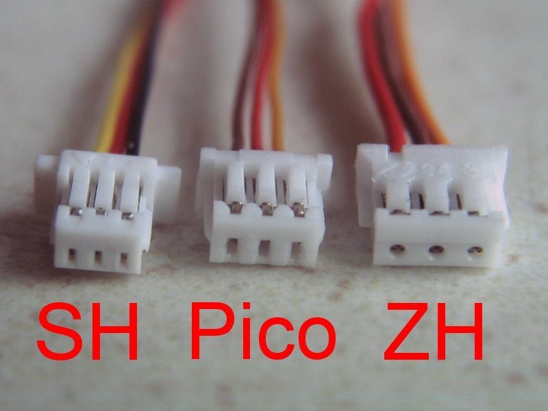
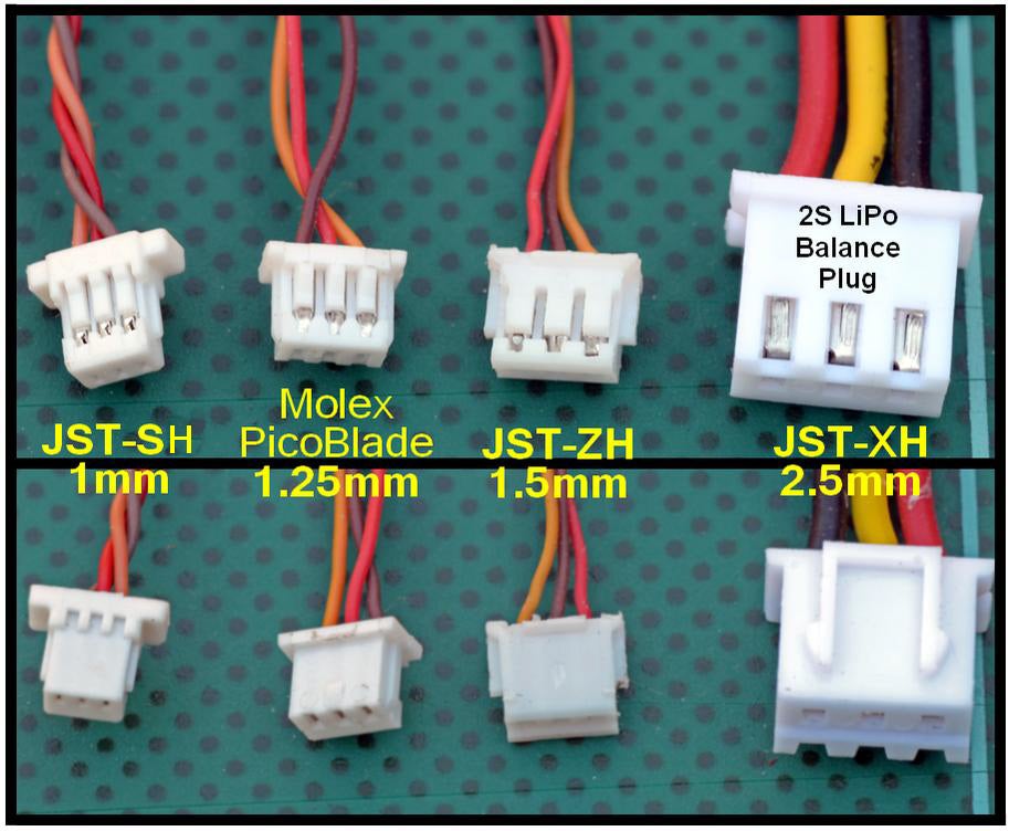
Every kind of micro connector imaginable.

EasyStar Brushless Outrunner
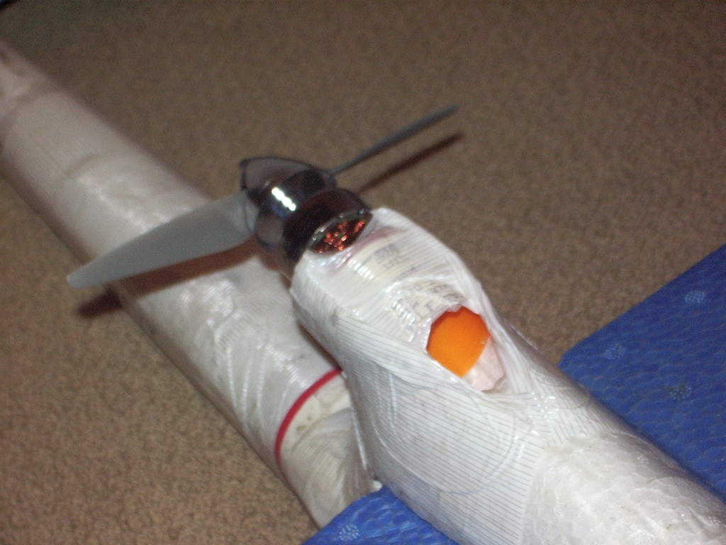
Monday, July 18, 2011
Interesting battery wiring guide

All about lipo balance connectors
 TJinTech has a great article on this, with lots of nice diagrams like this one.
TJinGuy's great website
Here's a website with lots of nice technical details. Especially interesting are his articles on charging and RC / battery wiring. Check it out! Here's a sample of one of his wiring diagrams:

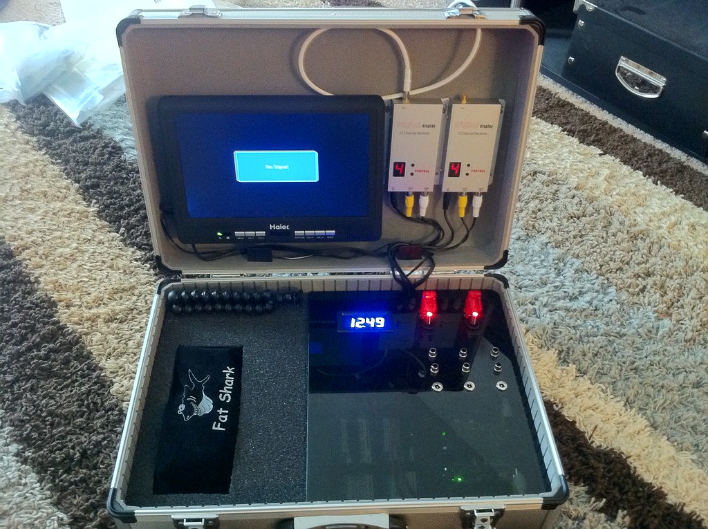
CrazyJ's new FPV all-in-one ground station box
Looks very nice! Self-contained, self-powered, includes a 10-inch monitor as well as fat shark glasses.
Details on RCGroups.
Details on RCGroups.
Beacon Foam-Tac Glue

They say:
Beacon Foam-Tac Glue bonds Depron, EPS, EPP, XPS, EPO, and many other kinds of foam quickly & cleanly. It does not attack/melt/dissolve foams, and when dry it remains flexible and clear. It's also great for bonding carbon fiber.
SUPER STRONG BOND - FOAM-TAC creates a super strong bond that is like welding the foam together. Make a Butt-Joint and you won't be able to find it later, stronger than the foam itself once it's cured.
LESS IS MORE - Always dries clear, simply apply a thin amount of FOAM-TAC to one side of the joint and gently press together. Pull the joint apart then press together again. That’s it. You don’t have to wait for the glue to get tacky.
My [note: this is filadelfosrc writing] own personal observations about Foam-Tac:1. It's a thick clear goo, reminds me of shoe-goo in it's consistency, but a little thinner.
2. Even though it's thick, when you pull the bottle away, it doesn't have any stringys to deal with.
3. Once bonded, you will not see the seam line & have no idea that it was ever two separate pieces.
4. Even though it forms a strong & permanent bond, the glue remains flexible & clear. I have used it to re-attach a broken aileron, and the aileron
functions just as it did before re-attaching (I actually glued the aileron straight onto the wing, knowing that it would still flex after Foam-Tac cured).
5. The bottle instructions say it takes 10-20 minutes to form a strong bond, but in my experience it happens in as few as 10-20 SECONDS, so that may be a typo.
6. You don't need to use much glue at all, I use far less of it than if I were to use a foam-safe CA for the same task.... and there's no need for any
accelerator.
Resistor Mod, fix for Turnigy 9x trainer port

Update: I modded my unit so the radio is purely module based; This lets me just pop out the module, so I've lost interest in doing this.
Sunday, July 17, 2011
Trainer Switch mod for Turnigy 9x
Strangely, the 9x trainer switch operates differently than most radios. By default, control is given to the student, and the instructor must pull the switch up to take control.
You can reverse the switch, but then you'll have one switch backwards for the infamous "switch error" startup mode. (actually, I'm used to that mode now and rather like it!).
 Here's a simple hardware mod using a spring and two pieces of plastic tubing to hold the switch in instructor mode. It's from a video review by Thomas Lombardi. Trainer switch discussion starts @3:34, the solution starts @4:42.
Update: I installed er9x which allows the trainer switch to be set properly.
You can reverse the switch, but then you'll have one switch backwards for the infamous "switch error" startup mode. (actually, I'm used to that mode now and rather like it!).
Update: I installed er9x which allows the trainer switch to be set properly.
ScrtSqrl's cheap pan-only, crazy-simple, zero-drift Head Tracker
Here's the original CGroups link and an update where ScrtSqrl unveiled his nifty head tracker. Genius!
 Basic Idea:
Vimeo link: http://vimeo.com/925056
- take a control (e.g. flaps) pot out of your radio
- extend the wires so it will reach your head
- add a lever and attach it to your hat
- add a bungee cord, attach to your radio
- attach cam servo to appropriate channel (e.g. flaps) on radio
Vimeo link: http://vimeo.com/925056
Sunday, July 10, 2011
A nice quad stand

Subscribe to:
Posts (Atom)