
Showing posts with label servos. Show all posts
Showing posts with label servos. Show all posts
Tuesday, October 23, 2012
Servo Board as Brushed ESC or LED controller
Tuesday, May 1, 2012
Miles of Free Servo Wire!

For me it's OK, I'm using it to make some custom receiver/APM connectors. I'll make pin 1 be the odd color on each side.
I use this great servo crimp kit from Hansen Hobbies.
The plastic part is sold as:
Harwin M20-1061200 12 PIN SIL HOUSING
The "12" in the part number goes from 01 to 12, and indicates the number of slots. I found the best value is to buy the 12 slot units and trim them down to size. They cut easily with a box cutter.
Friday, October 28, 2011
The Servo Database
Friday, May 27, 2011
Elevon / V-Tail Mixing Calculations
update: moved this into its own post. original elevon description here.
a = x/2 - y/2
b = x/2 + y/2
where

Calculating Elevon Motion
There are two calculations, one for each elevon:
There are two calculations, one for each elevon:
a = x/2 - y/2
b = x/2 + y/2
- a = left elevon deflection,
- b = right elevon deflection,
- x = aileron position (-1 = far left, 0 = centered, 1 = far right),
- y = elevator position (likewise, -1 .. 1)
Deriving the Elevon Calculation
I couldn't find the above formula anywhere on the web, probably because it's so obvious to everybody but me. Here's how I figured it out. Real mathematicians would do it much easier I'm sure!
First, look at the inputs and outputs. The above video shows the endpoints and midpoints of the two axes.

which gives us this table for the values of A and B:
a,b = f(x,y):
x=-1.0 x=0.0 x=1.0
y=1.0 -1.0, 0.0 -0.5, -0.5 0.0, -1.0
y=0.0 -0.5, 0.5 0.0, 0.0 0.5, -0.5
y=-1.0 0.0, 1.0 0.5, 0.5 1.0, 0.0
x=-1.0 x=0.0 x=1.0
y=1.0 -1.0, 0.0 -0.5, -0.5 0.0, -1.0
y=0.0 -0.5, 0.5 0.0, 0.0 0.5, -0.5
y=-1.0 0.0, 1.0 0.5, 0.5 1.0, 0.0
Showing only the values for A, we notice that there's a pattern across the rows, namely that it increments by .5 each row, as X varies from -1 to 1. So, we can start with "+ x/2" for each of the rows, for some value of Y.
a = f(x,y):
-1.0 -0.5 0.0
-0.5 0.0 0.5
0.0 0.5 1.0
-1.0 -0.5 0.0
-0.5 0.0 0.5
0.0 0.5 1.0
Likewise, we can see the same pattern for the columns in the other direction. Fiddling a bit, I came up with -y/2 + x/2 which of course simplifies to x/2 - y/2. I guessed there was a similar pattern for B, and tried a few variations of adding and subtracting x/2 and y/2. until I confirmed that x/2 + y/2 worked.
Here's a bit of python that reproduces the table above:
for x in (-1.0, 0.0, 1.0):
for y in (1.0, 0.0, -1.0):
a = x/2 - y/2
b = x/2 + y/2
print a,
print b,'\t\t',
print
for y in (1.0, 0.0, -1.0):
a = x/2 - y/2
b = x/2 + y/2
print a,
print b,'\t\t',
Sunday, May 15, 2011
Elevon / V-Tail Mixing
Here's what an Elevon or V-Tail/ mixer does. You can do it with your radio if it has that feature, or with an electronic hardware mixer. Here's the HobbyKing Mixer in action:
 If you're hardcore old school, you can do pure hardware mixing with this Dubro V-Tail kit ("23 piece kit"). NightFlyyer has a nice video (where??) showing one of his classic planes with hardware mixing.
Elevon Action
The elevator control will move both elevons equally up or down. When the aileron control is centered, pull the elevator back, then push it forwards. You will see the elevons go up, then down. The plane will be level across the wings, and pitch up and down.
The aileron control will move the elevons in the opposite direction. With the elevator centered, move the aileron control left, then right. When the stick is to the left, you will see the left elevon move up and the right elevon move down. When the stick is to the right, the left elevon will be down and the right elevon will be up. The plane will be level, rolling left and right.
When both the elevator and aileron move, the elevons combine the motion of the two. For example, pull the aileron left; you will see the left/right elevons move up/down. Keeping the aileron left, pull the elevator back. Both elevons will move up the same amount, keeping the deflection set by the aileron.
Motion Rules:
The same calculations for translating aileron/elevator to elevon wing surfaces will translate joystick controls to tank-style left/right wheel/tread motion.

Elevon Action
The elevator control will move both elevons equally up or down. When the aileron control is centered, pull the elevator back, then push it forwards. You will see the elevons go up, then down. The plane will be level across the wings, and pitch up and down.
The aileron control will move the elevons in the opposite direction. With the elevator centered, move the aileron control left, then right. When the stick is to the left, you will see the left elevon move up and the right elevon move down. When the stick is to the right, the left elevon will be down and the right elevon will be up. The plane will be level, rolling left and right.
When both the elevator and aileron move, the elevons combine the motion of the two. For example, pull the aileron left; you will see the left/right elevons move up/down. Keeping the aileron left, pull the elevator back. Both elevons will move up the same amount, keeping the deflection set by the aileron.
Motion Rules:
- elevator back: elevons up
- elevator forward: elevons down
- aileron left: left elevon up, right elevon down
- aileron right: right elevon up, left elevon down
The same calculations for translating aileron/elevator to elevon wing surfaces will translate joystick controls to tank-style left/right wheel/tread motion.
Monday, May 2, 2011
My Servo Testbed
While fiddling around with the Ardupilot Mega it was handy to plug in servos to see if everything was behaving as expected. Having a big bundle of loose servos wiggling around made it troublesome to see exactly which one(s) were moving. I hotglued some to a base, making it easier to see what servos were moving, and how much.
Thursday, February 17, 2011
Crimping Connectors
Deluxe Crimping Tool:
Chris Hansen has written the most amazing guide to crimping, servo connectors, and JST connectors I've seen. He's like the Beethoven of crimping and connectors!
The link above points to his really excellent crimping tool. Crimp kits (what I've bought... be sure and get a wire stripper if you don't have one for the tiny gauge wire) are here.
He's got a splendid guide, A Brief Discourse on Connector Antics (pdf). I wish there were this level of detail on everything in RC land!
"This is the best crimping tool we've ever used for making servo connectors. The ratcheting hinge lets you lock in the terminal first, then insert the wire. This tool gives you a lot of leverage so every crimp is extremely strong, but is comfortable and easy on the hands even after a lot of use. If you're going to be making a lot of connectors then this tool is well worth the investment - take a look at the comments below. Tools of this quality usually cost over a hundred dollars."
Friday, February 11, 2011
Pololu - Micro Maestro 6-Channel USB Servo Controller (Assembled)

"The six-channel Micro Maestro raises the performance bar for serial servo controllers with features such as a native USB interface and internal scripting control. Whether you want high-performance servo control (0.25μs resolution with built-in speed and acceleration control) or a general I/O controller (e.g. to interface with a sensor or ESC via your USB port), this tiny, versatile device will deliver. The fully assembled version ships with header pins installed."
Wednesday, December 1, 2010
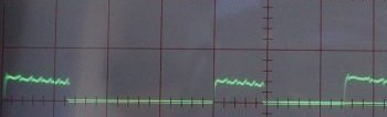
Servo Protocol Notes

- pulse is 1ms (full left) to 2 ms (full right). 1.5ms pulse is centered.
- pulse rate is typically 50 hz (ie, 50 pulses/sec)
- overpulsing can heat up analog servos
- QUESTION: it seems digital servos don't have to be refreshed. Do analog servos always have to be refreshed? I tried sending a single pulse, and an HX-900 analog servo seemed to hold its position. Perhaps I was doing something wrong?
http://www.rcheliwiki.com/Servo_protocol
Saturday, November 20, 2010

Monday, November 1, 2010
Peak Servo Current Tests
Thursday, October 7, 2010
Basic Servo Motion
Stick/Servo Relationship
Non-Reversing Installation
Plausible Rudder/Elevator Combinations
rudder   L = CCW, R = CW
aileron  L = CCW, R = CW
elevator F = CCW, B = CW
Non-Reversing Installation
rudder             elev
servo stem  horn   servo stem   horn
----- ----  ----   ----- ----   ----
left  top   left   left  top    bottom
right top   right  left  bottom top
down  left  left   right top    top
down  right right  right bottom bottom
                   up    left   top
                   up    right  bottom
                   down  left   bottom
                   down  right  top
Plausible Rudder/Elevator Combinations
DRR/DLB (inverted, for ezflyer)
LTL/RTT (flat, on top, 300s)
RTT/RBB (2 rights, above and below wing)
LTL/RBB (stacked, flat, around wing)
LTL/LBT (left, high, up and down)
Best configuration for RET (rudder/elevator/throttle) flyer (e.g. Blu-Baby) with push rods on outside of plane
rudder             elev
servo stem  horn   servo stem   horn
----- ----  ----   ----- ----   ----
left  top   left   right top    top
Tuesday, August 3, 2010
Controlling Servos

Bonus:
- Electric Motors 101 -- DC, AC, brushless, servo, stepper, more...
Sunday, July 25, 2010

Monday, July 5, 2010
By The Numbers: Servos
- Dimension: height, weight, length.
- Weight: and how much it weighs.
- Operating Voltage: electrical input range. for planes, this is almost always 4.5-6.0 volts.
- Operating Speed: how fast the servo motor turns. this measured in "seconds to rotate 60 degrees." often, there are two measurements, one for 4.5 volts (lower) and one for 6.0 volts. Be careful when there's only one number given, to make sure which voltage is being reported.
- Stall Torque: How hard the servoc can twist. At the given number, the servo will stall. The measurement is how much force is done from a particular arm radius. Like speed, there are often two numbers specified, for 4.5 and 6.0 volts.
- MG usually indicates "metal gear"
- Digital servos provide faster response, tighter accuracy, and higher "standing" torque at the cost of increased power consumption and a high-pitched squeal when operating.
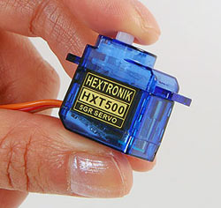
- For small park fliers and foamies, the standard 9g and 5g servos are fine, e.g. the HTX-500 and HTX-900.
- Dimension: 22.8x12x29.4mm
- Weight: 15.8g
- Operating Voltage: 4.5 - 6.0V
- Operating Speed: 0.13sec/60°at 6.0V
- Stall Torque: 54.12oz-in @ 6.0V (3.9kg-cm)
Subscribe to:
Posts (Atom)