Sunday, August 31, 2014

Next Gen 1S Super Charger Coming Up!

epilot@rcgroups notes a new lipo charging solution over at banggood. 10 pieces for less than $10!  I'm going to get a batch and try two things:

  • Next Gen Super Charger, even lighter weight than the old one.
  • Embedded Lipo Charging for the ArrMote.

notes:
  • resistor R3 determines the charge current.
  • 1.2Kohm on board, meaning the charge current is 1000mA.
  • Substitute R3 as per the Rprog table in the data sheet to reduce charge, e.g. 5Kohm = 250mA charge current.
  • lowest charge rate = 130 mAh
  • boards have an overcharge protection circuit.

Here's the TP4056 Data Sheet and the current table.

RPROG (k) IBAT (mA) 
10         130 
 5         250 
 4         300 
 3         400 
 2         580 
 1.66      690 
 1.5       780 
 1.33      900 
 1.2      1000


blogodex = {"toc" : "Charging", "idx" : ["Super Charger", "1S Charger"]};

Monday, August 25, 2014

Testing a Bluetooth Module

Here's how to test a Bluetooth module.
  • Short TX with RX on the module.
  • Power it up with 5V. ("+" and "-").
  • Bind to computer's Bluetooth.
  • Open a serial terminal (screen on Mac, putty on Windows)
  • No need to set baud rate, any rate will work.
  • Type on the console.  Every character will echo back since TX and RX are shorted together.
blogodex = {"toc" : "Bluetooth"};

Thursday, August 21, 2014

Hooking up the ArrMote

Here's how to set up the Arrmote.  Pictures forthcoming!  This page a Work in Progress!

Parts

Base

  • Arduino Pro Mini 3.3
  • Battery, 3.3V - 12V
The Pro Mini should have pins A4 and A5 on the top.
The Pro Mini should have a splitter on VCC, or a "long pin" on VCC.
The Pro Mini can optionally have a "long pin" on GND for ease of connection.

If you have two "long pins" it tidies up the assembly since the Nunchuck can be wired from the top and the nRF24L01+ can be wired from the bottom.

Nunchuck
  • Nunchuck
  • Nunchuck Adapter with header pins
  • 4 wire F-F cable
Radio
  • nRF24L01+
  • 100nF ceramic capacitor
  • 7 wire F-F cable
(tentative) solder the capacitor across GND and 3.3V on the nRF board.

Software Setup


You can start by testing your Nunchuck and Radio as described (here and here, coming).
  • Edit the sketch (name)
  • Modify the radio channel assignment.  If you are in the robotics class, your robot kit has a number.  Use use channel 3*RobotNumber (e.g. robot 1 = channel 3, robot 2 = channel 6, etc).
  • Upload this sketch AND DISCONNECT YOUR FTDI CABLE.

Connections

Attach the Nunchuck to the Pro Mini using the 4 wire cable and Nunchuck Adapter. (details here)
  • "+" : VCC
  • "-"  : GND
  • "d"  : A4 (top, farthest from header)
  • "c"  : A5 (top, closest to header)

    Attach the nRF24L01+ to the Pro Mini  (details here)
    • 1 : GND
    • 2 : VCC
    • 3 : pin 9
    • 4 : pin 10
    • 5 : pin 13
    • 6 : pin 11
    • 7 : pin 12
    • 8 : UNUSED
    Attach the battery to the Pro Mini
    • "+" : RAW
    • "-" : GND
    One the power is attached, your unit should be operational.  (test program tba)

    blogodex = {"toc" : ["ArrBot", "ArrBot Syllabus"], "idx" : ["nRF24L01+", "Nunchuck"]};

    FTDI, VCC, and the Arduino Pro Mini

    This project has been the first one where I've used a 3.3V Pro Mini.  There's some important things to keep in mind regarding power input.
    • Power input on RAW can be 3.3V - 12V.  It will be regulated to 3.3V.  Specifically, VCC will be 3.3V
    • Power input from the FTDI connector is not regulated. If you are using a 5V FTDI connector VCC will be 5V!
    • In general you can get by with using a 5V FTDI cable on a 3.3V Pro Mini.  It's out of spec but is generally accepted as working.
    • You can't use a 5V FTDI if you are powering a 3.3V device from VCC!

    Here's a workaround if you're stuck with a 5V cable and want to use it to power a Mini that has a 3.3V device on VCC.


    Remove the VCC line from the FTDI cable.  Gently lift the plastic tab and the  wire with attached connector will slide out.  If you have an extra single-ping cable protector (take one off a female-female breadboard wire if you've got one) you can insert the VCC connector in there.  You could also use some small heatshrink to cover it.  You could let it go bare, but be careful not to short it out.


    Attach the FTDI cable (minus the removed VCC) to the Pro Mini as usual.  Attach FTDI VCC to Pro Mini RAW.

    Check the voltage on Pro Mini VCC.  It should be 3.3V, regulated by the Pro Mini.


    The Sparkfun product page has this note in the comments:

    Q: Are the rx/tx lines 5V tolerant? I want to know if it is possible to program this with a 5V FTDI board, without needing to get an additional 3.3V FTDI just for this board. 
    A: Yes, the only difference in the 3.3V and 5V Pro Minis is the crystal and the voltage regulator. Since the FTDI bypasses the regulator the only difference is the speed the run at. The ATMega328 is fine at 5V. Keep in mind if you have 3.3V on VCC and 5V on the I/O pins that is technically out of spec (you shouldn't put more than VCC on the I/O pins), but will probably work as well. Keep in mind that the 5V FTDI will put 5V on the VCC line, so make sure you don't have any 3.3V only devices connected when you do this.

    blogodex = {"toc" = ["FTDI", "Arduino"], "idx" = {"ArrBot", "Electronics", "Voltage", "No Hack Too Cheap"]};

    Monday, August 18, 2014

    FrSky X Series Failsafe Modes

    The X8R and most FrSky receivers offer 3 options for failsafe.

    1. They default to hold last good command.
    2. You can program a set failsafe position via the Taranis, or pushing the f/s button on the receiver while holding the channels where you would like them.
    3. Push the F/S button on the receiver when the transmitter is turned off, and the receiver will not output anything when in failsafe. This is handy for many flight controllers to trigger a safety mode.

    Courtesy of rotozuk.  I didn't know about the third one.

    blogodex = {"idx" = ["FrSky", "Failsafe"]};

    Saturday, August 16, 2014

    ArrBot: Catchup Class

    We inserted an extra class after class 3 to give everybody a chance to catch up.  Here's everybody hard at work.

     The goal was to have these parts ready

    • 3D printed body
    • two working continuous rotation servos
    • Arduino micro
    and get everything assembled.

    Here's a few ArrBots in various states of completion.  This one is running the servo testing program to get the calibration values.
     Servos in place.  You can assemble the drive wheels either before or after they're attached to the servos.
     More servo testing!  Get that right and everything is easy.
     Here's the battery case mounted on the frame.  With this type of battery case you should use the wide body.
     We're using 3M Dual Lock to put everything together.  It snaps together and gives a better fit than Velcro, but just about anything will work if it holds the pieces together.
     Downloading the test drive program.  With all the pieces assembled, you can write an Arduino program to drive the ArrBot around.
     We're using 5V Arduino Pro Micro clones.  That's a mistake.  We'll be swapping them out for 3.3V units so that we can use either a Bluetooth or nRF24L01+ unit.  I think using a Mini is also better, since we're using a Mini in the remote control unit and we already have FTDI cables.
     Getting ready for the next class, attaching the nRF unit.


    blogodex =  {"toc" : "ArrBot", "idx" : "ArrBot Class"};

    Friday, August 15, 2014

    Troubleshooting Mac FTDI Driver Problems

    Symptom

    Can't upload, with this output:

    avrdude: Send: 0 [30]   [20] 
    avrdude: Send: 0 [30]   [20] 
    avrdude: Send: 0 [30]   [20] 
    avrdude: ser_recv(): programmer is not responding
    avrdude: stk500_recv(): programmer is not responding

    avrdude done.  Thank you.

    Diagnosis

    According to http://www.enttec.com/support-center/kb/article/108-OS_X_Mavericks_(10.9)_-_IMPORTANT Apple has developed their own FTDI drivers for OSX 10.9. These drivers are problematic.

    Solution

    Type the following commands into the terminal:

    cd /System/Library/Extensions/IOUSBFamily.kext/Contents/PlugIns 
    sudo mv AppleUSBFTDI.kext AppleUSBFTDI.disabled 
    sudo touch /System/Library/Extensions

    Restart your computer.

    Install the original FTDI Virtual Com Port drivers found here: http://www.ftdichip.com/Drivers/VCP.htm

    Start Arduino and program as you always have.

    Credit: Adam S.
    Details: http://forum.arduino.cc/index.php?topic=198539.0

    Wednesday, August 13, 2014

    ArrBot: nRF24L01+ notes

    Some random notes.  Pay attention to the orientation of this illustration.  The pins are usually on the other side.

                                pins     pin names         arduino connections
     --------------------------------
    | antenna                   2  1 |   (2=VCC,  1=GND)   (2=VCC,    1=GND)
    | antenna                   4  3 |   (4=CS,   3=CE)    (4=pin 10, 3=pin 9)
    | antenna                   6  5 |   (6=MOSI, 5=SCK)   (6=pin 11, 5=pin 13)
    | antenna      crystal      8  7 |   (8=IRQ,  7=MISO)  (8=none,   7=pin 12)

     --------------------------------

    //   1 - GND
    //   2 - VCC 3.3V !!! NOT 5V
    //   3 - CE to Arduino pin 9
    //   4 - CSN to Arduino pin 10
    //   5 - SCK to Arduino pin 13
    //   6 - MOSI to Arduino pin 11
    //   7 - MISO to Arduino pin 12
    //   8 - UNUSED

    Tuesday, August 12, 2014

    Concord Model Engineers Minutes, July 2014

    CONCORD MODEL ENGINEERS MONTHLY MEETING MINUTES

    Tuesday, August 12, 2014

    CALL TO ORDER:  7:30 pm
    ATTENDEES: 20     GUESTS:  0

    MEETINGS:

    Monthly meeting, Second Tuesday, 7:30 at Concord Airport Terminal.

    Friday Fun Fly, Third Friday, 7:00 - 9:00 pm.
    Gym at the Church of the Nazarene, 1650 Ashby Dr., Concord

    Fun Fly this month on August 15.


    Stiffening a Wing with CF

    rtfmaero@RCG provides this pointer for stiffening a wing by gluing CF strips to the top and bottom of the wing. Somebody else had made a similar suggestion.  He writes:

    "if you are looking to make the wing panel really stiff, then abandon any thought of a beefy (single) internal CF rod. Go instead for two flimsy SURFACE MOUNTED CF rods - spar caps - (one on each surface of the wing). Doing so will make your wing completely stiff, able to withstand maybe 100kg (this might translate to perhaps 100g G's). I have used a single 1mm x 5mm CF sliver bonded to the top surface and to the underside of a wing, and the panel is as stiff as a solid plank of wood. It just doesn't bend...

    "The next step is to make sure the wings don't bend in the middle, where they join. To do that:  Get a new CF rod; Cut it in half; Lay BOTH halves side by side in the inner section of the wing. I had to cut a second channel in the recessed area to make room for the second spar rod. This will make the wing join section very stiff."


    blogodex = {"idx" : ["Bixler 2", "Wing Stiffening"]};
    An interesting discussion regarding Forgues Research's custom Taranis case.

    blogodex = {"idx" : ["Taranis", "Case customization"]};

    Monday, August 11, 2014

    Concord Model Engineers Minutes, July 2014

    CONCORD MODEL ENGINEERS MONTHLY MEETING MINUTES

    Tuesday, July 8, 2014

    CALL TO ORDER:  7:30 pm
    ATTENDEES: 20     GUESTS:  0

    MEETINGS:

    Monthly meeting, Second Tuesday, 7:30 at Concord Airport Terminal.

    Friday Fun Fly, Third Friday, 7:00 - 9:00 pm.
    Gym at the Church of the Nazarene, 1650 Ashby Dr., Concord

    Fun Fly this month on August 15.

    Sunday, August 10, 2014

    Ahoy, Mates!

    My neighbor is moving from San Francisco to join a startup in Chicago.  Weird, right?  and Brrr!

    But he very kindly gave me this sailboat, which has been sitting in his garage for a long time.  What a splendid fellow!
    It needs to be cleaned up, but all the parts seem to be in place and the rigging seems intact.  Once I wrap the ArrBot, I'll give it a go and report back here.  Initial impression: those are some pretty massive servos!
    And not just a pretty yellow sailboat, but a glider as well!  There's a few tears in the covering, but I'll take it to the Concord Model Engineers and see what they have to say about it.

    Thanks Blake!


    blogodex = {"idx" : "Sailboat"};

    Saturday, August 9, 2014

    Connecting Things to Breadboards

     Often we want to connect a servo-style connector to a breadboard.  It could be a component with such a connector (like a servo!), or perhaps something with power (such as a battery pack) that we might not want to have with an exposed lead.

    The easiest way to do this is with a header pin.  Use some tweezers or pliers to center the plastic.  If that doesn't work for your application, soldering a pair of headers might be an alternative.
    Each half of the header will be just long enough so that it will both stay in the breadboard and also stay attached to the servo connector.

    One problem: When we pull out the servo connector, it will usually hold on tighter than the breadboard, and the header will come out. This can be troublesome if that end is connected to a battery pack or other powered line that you don't want to short out.  In that case, you can solder two headers together (shown on the right in the first picture).  The breadboard will have a stronger grip, and it's a bit easier to make sure the pins don't pull out when you pull the connector off.


    blogodex = {"idx" : ["breadboards", "prototyping"]};

    Arrbot: Assembling the Body

    Now that we've got the body printed and servos modified, it's time for some relatively easy assembly work.  Rewarding too... finally we'll start to have something that looks like a  robot!  In addition to the body and servos, we'll need two treads, two servo arm kits, two front wheels, and two drive (back) wheels.  The drive wheels have two pieces.

    Read on to see the step by step instructions.


    ArrBot: Downloading and Setting Up the Software

    The ArrBot software lives here. and is zipped up here.

    After you fetch it, you need to install three libraries.  Do this three times in the Arduino IDE:
    • Sketch / Import Library / Add Library
    and select each of these folders in turn.
    • ArrHeader
    • ArrServos
    • ArrNunchuck


    If you're familiar with installing libraries manually, you can just copy those three folders to your Documents/Arduino/library folder.

    Once you have done that, you should be able to build and upload any of the programs in the ArrBot distribution.

    blogodex = {"toc" : "ArrBot", "idx" = "Arduino"};


    Friday, August 8, 2014

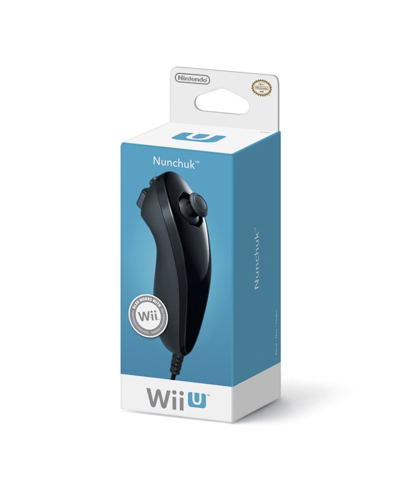
    How to Buy a Genuine Nintendo Wii NunChuck

    It's more difficult than it seems!  I bought a batch for class from Amazon, and even though the vendor said "Nintendo" it turns out they're counterfeit. And they're crap too,  can't get anything out of them. grr!!  Thankfully I had a genuine nunchuck at home with my Wii, so I was able to test things out.

    To find authentic units, go to the official Wii U accessories page on nintendo.com.  They've got links to products at Amazon, Gamestop, Target, and Walmart.


    blogodex = {"idx" : ["Wii NunChuck", "counterfeits", "GRRR!!!"]};

    ArrBot: Nunchuck, Phase 1

     Phase 1 of setting up the Nunchuck-based ArrBot remote control is getting the Wii Nunchuck set up and operational.  We're using the most excellent WiiChuck adapter.  Solder 4 pins onto the unit.  Do it backwards from this picture and you will more easily see the silkscreened pin IDs when the unit is on a breadboard.
     There are four wires to attach to the Arduino.
    "+": either VCC (on a 3.3V arduino), or 3.3V (on a 5V arduino)
    "-" - GND
    "d" - SDA (A4 on Pro Mini)
    "c" - SCL (A5 on Pro Mini)

    Note: Pro Mini I2C pins are SDA (A4) and SCL (A5).
     A4 and A5 are in a weird place on the Pro Mini.  Look on the bottom and you will see where it is labelled.  I soldered the headers so that the went above the board, allowing the Pro Mini to sit in a breadboard.
     Here's the wires installed.  For initial testing, the Pro Mini doesn't need to be seated in a breadboard.  This may prove useful to us.  We may be able to hook up the radio, battery, and Nunchuck lines directly onto the board and put everything into a tidy little case.  If that's true, we may redo the pins to make the case as small as possible.
     Attach the FTDI cable and run the ArrBot Nunchuck Tester.  Open the serial monitor. Move the joystick, press the buttons, and shake the Nunchuck along all three axes.  You'll see current, max, and min values.  We'll use those later to calibrate.

    Note:  There are a ton of aftermarket nunchucks and counterfeit units being marketed as from Nintendo.  A lot of the clones and counterfeits don't work.  My genuine nunchuck works well, and comes with a little instruction label attached to the cable.  If your nunchuck fails to produce good values in this program return it and get an authentic unit.  Good Luck, even on Amazon there are plenty of counterfeits being sold as Nintendo units. :( :( :(

    TODO: library setup

    TODO add screen shot of program running.

    Thursday, August 7, 2014

    ArrBot: Class 3 Notes

    Today's class will be a bit more entertaining than the last two classes.  Now that we have the components, we're going to assemble the robots!

    (pictures forthcoming!!)

    You should have prepared for class:
    • Robot body and wheels
    • Two CR servos
    Bring to class:
    • Robotics kit, including the above
    • Soldering stuff
    • Small (but not tiny) phillips screwdriver.  Look at the screws in the servo kit.
    • Sandpaper, medium and fine grit.
    • Hot glue gun, if you have it.  I'll bring some extra hot glue sticks if you don't mind sharing your hot glue gun.
    Building the Robot

    tl;dr: put all the 3D printed parts together and put the battery and breadboard on top.

    Front Wheels

    Fit the front wheels onto the axles.  Most likely they won't fit, and will need to be sanded down.  Even if they do fit, you will want to sand them to make the axle and the interior bearing surface of the wheel as smooth as possible.

    When each front wheel turns smoothly on its axle, use one of the "large" servo screws to attach the wheel to the axle.  You might have to open up the hole in the wheel a bit so that the wheel will turn freely.  Heating the screw a bit will allow it to screw smoothly into the axle.  Tighten the screws so that the wheels don't wobble, but not so tightly that they bind against the wheel.

    Put some dry silicone/teflon lubricant between the axle and the wheel.  Not too much, it gets a bit messy if you use too much.

    Drive Wheels

    The drive wheels come in two pieces.  Take the long servo arm and fit it into the slot.  Press the outside part of the wheel tight so that the servo arm is held firmly in place.  Trim any excess plastic off the servo arm.  Add a bit of hot glue to hold everything together.  The teeth should be centered on the wheel.  Attach the servo arm to the servo with the small screw in the servo package.

    Note that there's a wrong way to put the drive wheels together.  The gears should end up in the middle.  If the gears are touching the side, you've done it wrong.

    Mounting Servos

    You can do this in either of two ways.  If you have some extra screws, you can screw the servo onto the body.  There's a flat surface that will accept the screws.

    You can also just hot glue the servo to the body.  This seems to work fine as well.  Use a thin layer of hot glue, and press it tight with your fingers to ensure a square, tight fit.

    Battery Pack

    Solder or crimp a servo lead onto the battery pack.  Put "+" in the center and "-" on one side.  This will allow you to attach the battery to the breadboard on pins inserted into RAW and GND.

    Make sure your battery pack fits within the ArrBot treads.  If not, hot glue a bit of cardboard or other material the bottom of the breadboard (remove the paper backing covering the adhesive first) so that it clears the treads.

    The Stack

    Pull the paper off of the adhesive on the breadboard.  Put some Dual Lock on the top of robot body, top and bottom of the battery holder, and bottom of the breadboard.  Stack all this up and lock it tight.

    If you don't have Dual Lock, use some Velcro or any other stuff that looks like it might hold everything together.

    The Treads

    Finally, put the treads on the wheels.  Note that there's an indentation on one side of the tread, that should be on the inside and line up with the gear teeth.

    blogodex = {"toc" : ["ArrBot", "ArrBot Syllabus"]};

    Tuesday, August 5, 2014

    MacOS FTTI Installation

    Here's the installation guide. On page 3, use this link to get the dmg and select the appropriate file for your MacOS version.  10.9 seems to work with the release for 10.8.  You want the one that creates the virtual com port.


    Here's the error I was getting:

    avrdude: Send: 0 [30]   [20]
    avrdude: Send: 0 [30]   [20]
    avrdude: Send: 0 [30]   [20]
    avrdude: ser_recv(): programmer is not responding
    avrdude: stk500_recv(): programmer is not responding 


    blogodex = {"idx" : ["FTDI", "MacOS FTDI Drivers"]};

    Sunday, August 3, 2014

    ArrBot: Dual Servo Calibration

    Here's the process we'll use to calibrate the servos.  In phase 1, we'll do this the simplest way possible. There's two reasons for this:
    • Practically, we're coding the first iteration in a limited amount of time.  Tending towards simplicity is a good thing at this time.
    • For teaching purposes, it's good to have a couple of small single-purpose programs.  Later we'll combine everything into one program and put a cross-platform GUI.
    Measure the Left Servo

    Load the  Basic ArrBot Servo Tester.  There's a couple of values we're trying to find.
    • Find the midpoint where the servo is stopped.  Write down this value as MID.
    • Increase the value until the servo is at its maximum speed. Write down this value as HI.
    • Decrease the value until the servo is at its maximum speed in the other direction.  Write down this value as LO.
    • Calculate SPAN as HI - MID.
    • Hopefully, SPAN = MID - LO as well.  If not, choose the lower balue.

    Measure the Right Servo

    Get MID and SPAN for the right servo as above.

    Write the Calibration Data to the Arduino
    • Grab the Basic Servo Calibrator.
    • Fill in MID and SPAN for the left and right servos.
    • Don't worry about REVERSE.  You may need to set that later.
    • Run the program and the calibration data will be written to the EEPROM.
    • Watch the serial monitor and it will confirm.
    Now we're going to switch things up a bit.  First, we want to start thinking of motor speed in terms of percentage.
    • -100% = maximum speed reverse
    • 0% = full stop
    • 100% = maximum speed forward
    And we want to see if  if the two servos are working well together, i.e. if -100%,0%,100% produces the same speed on both motors.  We'll modify our servo test in two ways:
    • Add a second servo control.  Now we can test the left and right servos at the same time.
    • Change the control values to percentages.

    Assemble the Enhanced Servo Tester

    Start with the ArrBot Servo Tester. Duplicate the connections, so you have this configuration:
    • left servo: RAW, GND, Pin 9
    • right servo: RAW, GND, Pin 10
    This will be the basic ArrBot configuration.

    Test the Two Servos Together

    Run the ArrBot Dual Servo Tester (coming!)  It has the following controls.
    • v -- variable sweep from -100% to 100%
    • c -- set 0%
    • j, k -- subtract, add 1%
    • r -- cycle through channel reversal combinations

    blogodex = {"toc" : ["ArrBot", "ArrBot Syllabus"], "idx" = "Servo Calibration"};

    Nice LED/Resistor Calculator

    Parallel and Serial modes, pretty simple to use.  Very nice!

    http://www.hebeiltd.com.cn/?p=zz.led.resistor.calculator

    blogodex = {"idx" : ["led", "led resistor calculator"]};