Saturday, March 31, 2012

Turnigy Micro-Quad build, part 2

 Continuing from part 1... here's the power cable attached to the bottom of the board.


Check the voltage on the power pads, you should see full battery voltage.  You'll also notice that the positive pad is on the right looking down with the arm pointed at you.
 A lot of ESC wiring needs to be cut off in order to solder the ESC directly onto the frame.  It turns out this is a lot easier than it looks, so don't sweat it.
 Here's about how much to cut off for the power.  Put a blob of solder onto the pads, then cut and tin the ESC power wires.  Position the wired onto the blobs, touch your soldering iron to the wire, and the tinning solder melds smoothly with the blob on pads.
 Trimming the shrinkwrap a bit helped.
 To verify, plug in the battery and measure the voltage on the control cable.  it should be about 5 volts.
 Do the same thing to the three motor leads of the ESC.
 Do whatever programming (if any) is necessary on your quad controller board.  My notes on doing this for a KK Board are here.
 It seems you're supposed to attach the KK Board (if that's what you're using) onto the leg bolts, but they're too short.  I used a triple layer of double-sided servo tape.
 Attach your receiver and hook up your motors to the quad controller board.
 Now here's a very weird thing.  I trimmed the motor wires just as I trimmed the ESC wires, but I could not get the to tin at all.  I have no idea why this was -- are the wires coated?  Anyways, I mashed the wires into the solder.  I'm hoping this is good enough... if not and I have a cold solder joint I'll try and figure out the solder problem or buy another motor.
Fortunately, I had done just the one motor as an experiment.  For the other three motors, I tinned the ends without cutting the wire, and attached them while just folding the wires back.

This worked well and is what I recommend you do. (update: brosius85 points out that the motor windings are coated with varnish that's heat-resistant in order to handle the high temperatures of the motor.  That's why I couldn't just burn off the coating with the soldering iron.  Thanks Brosius85!)


Continued in part 3...

Friday, March 30, 2012

Turnigy Micro-Quad build, part 1

 I'd been looking for a small quad kit for a while... something that I could fly inside the house without making it sound like we were under attack.  When HobbyKing announced their micro-quad I thought I would give it a go.

It arrived very nicely packaged.
 And inside the package, everything very tidily laid out.  Fiberglass body parts, and an integrated power distribution setup.  More on this below.
 Parts List:


Update: Now there's a receiver-ready prebuilt ARF which includes a KK2 board.


Ikea-style instructions!

 Here's the power distribution part of the board.  The power side of the ESCs are soldered directly onto the PCB pads, and there's a spot for a JST connector to be soldered.
 The flip side (which is the top) has the four wires necessary to interconnect the positive and negative poles.
 The laser cut fiberglass turned out to be really easy to disassemble.  Wiggle the pieces a bit and they will twist loose with no problem.  I used a pair of small pliers to snap off the little connector pieces.


 Here's the power train, minus batteries.  Hobbyking sales hint if you're in the US:  If the batteries you need are so stocked, order them  separately, and get them from the USA warehouse.  This will speed up your order shipping from the International warehouse since there won't be any LiPos that will cause slow shipping.
Here's one set of everything.  Vendors must love multicopters, since they sell 4x or more of all the components!

I had planned on using the nice-looking spinners that came with the motors, but the props didn't fit.  I didn't want to spend time hollowing out the props so I'll use the included prop savers instead.  You won't need the included bullet connectors or shrink tubes.
 Here's my KK board, installed on my East Bay Standard control board carriage.  We won't need the carriage for this tiny unit!
 The King was out of stock on the M2x8 bolts and M2 lock nuts.  That's a shame, coz buying them locally cost an arm and a leg:  36 and 28 cents each, respectively... ouch!!  I tried fitting some cheaper imperial screws, but couldn't find any that were noticably cheaper that fit to acceptable tolerance.


 Snapping off the retaining pieces as noted above.
 Here's the frame dry-fitted together.   It holds together pretty nicely, so you can put off gluing the pieces together until after all the other construction steps.


 Here's the top shield.
 The holders were a bit wiggly.  After they're screwed onto the board it's pretty secure.
 Here's the included hardware.  It's everything needed except for the motor mount.
 Everything dry fitted together, with the top bolted on.
 Here's the leg mounts, assembled and ready to attach.
 The shield bolts seem a bit short.
 Everything attached, looking from the top.
The fully assembled frame, bolted but not glued.
 The motors, motor mounts, and spinners (which won't be used -- see the next step).

(UPDATE: ignore prop information below.  see part 2 where I recommend using a hammer to pound the props on.)

 Here's the prop... notice the tiny hole.  Let's try the prop saver!
 You will need a 1mm hex wrench to install the prop saver.  Put the big rounded end out.
 The motor includes an o-ring to attach the prop.  I've had much better luck with theraband prop savers.
The small prop hole doesn't fit onto the end of the prop saver, but if you wiggle the prop a bit it will fit snugly on the end.  Don't forget to balance the blades.


To be continued...

Thursday, March 29, 2012

Post #500!

While fiddling around with the blog settings this evening I noticed that I had 499 posts to this blog.  What a great opportunity to post this quick message and have it come out as number 500.

Thanks to all those who have helped me out from those days when I was trying to figure out which end of the plane to throw in the air first.  I really appreciate it, and am happy to have heard from so many people who have told me that they've benefitted from something I've written.  Remember, it's just an ongoing journal of my own ignorance!

This blog's first post was on July 1, 2010 and had some links to those crazy Utah electric combat fliers.  I still want to travel there and fly with those guys!


Friday, March 23, 2012

FrSky Voltage Monitor, with OLED screen

Well this is rather nifty... a voltage montor that shows 1-6 cells on an OLED!  It's from FrSky and designed to be part of their telemetry system, but works fine on the ground as a voltage meter.  Not bad for less than $12... I had no idea OLEDs were so cheap!

FrSky 1-6 cell voltage monitor

Thursday, March 22, 2012

Prop Slot noise reduction

RCG thread showing how to reduce prop noise by shaping a curve in the slot.  Otto Diefenbach includes some nice video demos.

Basic idea: the center is cut very close, and the edges slope away.

Monday, March 19, 2012

Sunny Screen Update

Sunny day today, so I could do a quick test of the sunny screen cutout.  Here it is with sun shining on the right part of the screen, and the left part of the screen shaded.  So far, it looks like it may work!  I'll try modding the second laptop that runs the APM ground station software.


Here's what the back side looks like.  I've got it taped up, but I'll put a piece of clear plexiglass or somesuch on the final version.

Sunday, March 18, 2012

APM: the East Bay Standard Configuration

Here's how I've got my Turnigy 9x / Ardupilot Mega configuration set up.  I'm going to call it the "East Bay" configuration.

If you use this configuration and want a sticker drop me a line and I'll send you one!

9x Setup

(put link here)

Ardupilot Setup


    manual      rtl
    stabilized  auto
    fbwa        loiter

Arducopter Setup

(double check)

Video TX/RX fiddling

I think I've got just about everything needed for putting together the video Tx/Rx.  I've got both 1280 and 5.8 and will give them both a try.

I'll try all the various combinations of hooking things up, including direct connections from the cameras to the screen.  I imagine there will be much connectoring involved.

The diagram has all 8 possible connections among all the components.  I'll update as I get each one going.

FrSky installed, 9x module rejiggered

 Here's my FrSky module.  HK was out of the new model with telemetry, so I got the older model from Range Video.  Once the original 9x module was removed (more on that below), it was a simple matter to plug in the transmitter module and bind to the two receivers.
 I got the patch panel as well.
 Here's how the patch panel looks when installed.  I'll experiment with the range, it may be necessary to hold the transmitter a bit higher than usual?
 Here's what the transmitter module looks like from the side.  Very nicely, the  antenna mount points forward and there's a flat surface for the receiver to rest on.
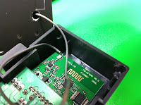
 Here's my rejiggered 9x module.  I should have taken some pics of the disassembly, but it's pretty straightforward.  Open the Rx case and loosen the screw that holds the antenna.  Open the module and remove the board.  Unsolder the antenna from the board, and remove the antenna and wire.  Don't bend or break the wire, it's actually a coax cable soldered onto two pads on the board.  Once the 9x module has been removed, you're good to use the FrSky module.
 I drilled a hole for the coax and ran the antenna through.  I epoxied the antenna over the hole, scoring the module cover and drilling some extra holes around the base for the epoxy to hold onto.

Here's an alternate method for removing the antenna that doesn't involve unsoldering and resoldering the connection.

 Resoldering the antenna cable needs a bit of care.  The two parts of the coax cable need to be soldered onto the two pads of the circuit board.  Study the board carefully before unsoldering and you'll see what needs to be done.

It turned out to be a lot easier than I thought it would be.  I didn't have to add any more solder or flux.  Hot glue the board into place as it was.
Here's what it looks like from the bottom.  Not quite as well as nice as the flat bottom of the FrSky module, but it doesn't seem to be too bad.  I'll point the antenna straight down when flying.