SailFlow.com - CA- sf central bay Wind Data
Berkeley Marina wind report.
Thursday, March 31, 2011


Sunday, March 27, 2011
Ardupilot Mega with Ardupirate-NG, software test
Hooray, we got the Ardupilot-NG load downloaded, built, installed, and configured. Next step: hook it up to the Arcticopter. Hint OTD: the Arduplane and Arducopter loads need different inputs on the control inputs. Channel 8 on both switch the APM into strict pass-through mode, definitely not what you want for multicopters!
Wednesday, March 23, 2011
Hooray, Ardupilot Mega 2.0-Beta works under VMware!


Video forthcoming!
Monday, March 21, 2011
Hooray, Ardupilot Mega hooked up via VMWare on Mac!

- fresh Windows 7
- VMware Fusion 3.1.2
Plug in the Ardupilot Mega to a USB port:
- specify that the device will attach to windows.
- the first time windows detects the APM, it will automatically download and install the proper driver.
- Typically, it will show up as COM3.
- Mission Planner
- Ardupilot Mega 2.0 (source)
- Aruduino 0022 (windows)
We also built and installed the APM 2.0 source and used the Arduino serial monitor to run the debug monitor. Set the Arduino serial monitor to Carriage Return / 115200 baud. Was able to correctly read the GPS position!
We wasted a fair bit of time because I confused my old busted Turnigy 9X (on its way to be returned to Hobby King) with the new replacement.
Next steps:
- test out radio functionality
- test ardupirates quad source
- hook up to xpilot
- figure out and order xbee stuff
Thursday, March 17, 2011
FPV flight 2
Video to come, here's a still shot... I crashed right away, but Andreas did a great job flying with his newly-padded goggles. The wind was pretty strong; he was able to hover almost directly overhead.
We fiddled with the patch antenna; it worked best to have someone (me in this case) kept it pointed at the plane. The glitchy area was exactly in the plane of the flat part of the antenna.

We fiddled with the patch antenna; it worked best to have someone (me in this case) kept it pointed at the plane. The glitchy area was exactly in the plane of the flat part of the antenna.

Wednesday, March 16, 2011
Adding a 3-position switch to a transmitter

Update: Wago Connector for Power Distribution

Executive summary: seems to work pretty well! And eliminates lots of soldering. The soldering itself isn't bad, but the bundle of soldered wires are big and bulky, and lose their flexibility where they're soldered.

There's a couple of good vendors on ebay selling them. I bought a box to reduce shipping. If you would like a pair of these for $5.00 including shipping, send me a note at my email under the "About" entry under "Interesting Things". I'll confirm with you that I still have some, let you know my paypal, and send them out.

I'm still interested in learning more about power distribution. My collected survey of systems is here.
About Me
Hi, I'm Mark Harrison, an RC enthusiast and computer programmer who lives in the lovely San Francisco East Bay.
Leave me a comment, or send me mail! marhar@gmail.com
I'm also marhar at rcgroups.
Leave me a comment, or send me mail! marhar@gmail.com
I'm also marhar at rcgroups.
Saturday, March 12, 2011
Turnigy 9x notes
Here are some notes on:
Backlight kit.
I got one, it's really nice! You have to install it yourself, but it's not very hard. Be careful if you're taking out the screws for the first time. Note that the PC board has two sizes of screws.
Receiver Polarity
Radio Knobs and Dials
If your throttle is reversed, you may have made a mistake when setting the sticks to mode 2. If you set the mode, DO NOT push menu when it asks to reverse throttle, just push exit.
Weird MODE?
On the screen, you may see you are in MODE 1 when first starting up. You're not in "mode 1" as in sticks, you're on "model 1". MODE=MODEL. This was what led me to me mess with the mode and end up reversing the throttle as mentioned above. Don't be fooled like I was!
Some people have recommended this as a superior alternative to putting NiCad batteries in the stock battery holder.
MIXING
Possible ArduPilot mix formula here:
http://rcav.posterous.com/programming-an-ardupilot-mode-switch-for-turn
FAILSAFE
Short story: failsafe only works in PPM mode. :-(
TODO
take some pics
Backlight kit.
I got one, it's really nice! You have to install it yourself, but it's not very hard. Be careful if you're taking out the screws for the first time. Note that the PC board has two sizes of screws.
Receiver Polarity
- Signal on top
- Ground on bottom
- channel 1 ailerons
- channel 2 elevator
- channel 3 throttle
- channel 4 rudder
- channel 5 (I assigned to GEAR)
- channel 6 (I assigned to THRO HOLD)
- channel 7
- channel 8
Radio Knobs and Dials
- thro hold (cut) left front bottom
- gear right front top
- pit trim left top dial
- hov throttle right front dial
- hov pitch left front dial
- To select the letter, do a "long menu", hold down the menu key for a half second or so.
- Some programmer has a lot to answer for!
If your throttle is reversed, you may have made a mistake when setting the sticks to mode 2. If you set the mode, DO NOT push menu when it asks to reverse throttle, just push exit.
Weird MODE?
On the screen, you may see you are in MODE 1 when first starting up. You're not in "mode 1" as in sticks, you're on "model 1". MODE=MODEL. This was what led me to me mess with the mode and end up reversing the throttle as mentioned above. Don't be fooled like I was!
- turn off transmitter
- plug ESC into channel 2
- bind plug into BIND
- add power to ESC
- Step back at least 6 feet (this seems IMPORTANT!)
- push bind button on back of transmitter
- power on transmitter
- wait for receiver light to stop blinking
- power off receiver
- power off transmitter
- remove bind plug
- power on transmitter
- power on receiver
- test!
Some people have recommended this as a superior alternative to putting NiCad batteries in the stock battery holder.
MIXING
Possible ArduPilot mix formula here:
http://rcav.posterous.com/programming-an-ardupilot-mode-switch-for-turn
FAILSAFE
Short story: failsafe only works in PPM mode. :-(
TODO
take some pics
Thursday, March 10, 2011

arr, it's the ardupirates!

- Working Sparkfun Magnetometer
- GPS hold
- Altitude hold with Barometer and Sonar
- Automatic camera leveling plus an automatic camera trigger!
- Ardupirates RCG thread
- Google Codebase
- Ardupirates Wiki
- Ardupirates Configurator (supports multiple hardware platforms)
- Ardupirates Installer
Wednesday, March 9, 2011
Setting up the Ardupilot software
The Ardupilot software uses the Arduino environment to compile and download to the Ardupilot board. Here's how to set up your environment for that.
Download and install the Arduino Software
 Build the Ardupilot Software

Build the Arducopter Software
Download and install the Arduino Software
- The software is here: http://arduino.cc/en/Main/Software. Get the latest version. There are pre-compiled binaries for Mac, Windows, Linux-32 and Linux-64.
- I'm using a Mac. It's a DMG with the Arduino software, ready to drag into your Applications folder.
- There's also an enhanced FTDI USB driver. It's a package that installs using a password.
- This is a software project, and tidy housekeeping now will pay off handsomely in the end!
- I chose this as my base directory: $HOME/Dropbox/projects/ardupilot. I'll call this $TOP below.
- Later we'll set up a SVN checkout.
- For now we'll just unzip the Ardupilot and Arducopter distributions here. I'll save local copies of the zipfiles in $TOP/dist.
- From here: http://code.google.com/p/ardupilot-mega/downloads/list.
- The following is what I did from the mac command line... Adust to your favorite workflow.
- cd $TOP/dist
wget http://ardupilot-mega.googlecode.com/files/ArduPilotMega1.02.zip
cd ..
unzip dist/ArduPilotMega1.02.zip
- From here: http://code.google.com/p/arducopter/downloads/list. I grabbed Arductopter RC2.zip.
- Download and unzip as per above notes.
- The most painful step in getting things set up is getting the libraries installed.
- Here's the biggest pain in the whole software setup. There might be a better way, but this is an area where the Arduino software could stand improving.
- Find your Sketchbook path.
- On mac:
grep sketchbook.path ~/Library/Arduino/preferences.txt
sketchbook.path=/Users/mh/Documents/Arduino - Go to the sketchbook path just discovered.
- mkdir libraries, if it does not already exist
- cd to the libraries directory.
- copy all the folders in the ArduPilot project libraries directory here.
$ cp -rp ~/Dropbox/projects/ardupilot/1.0-BETA/libraries/* . - restart the Arduino program. These libraries should now be available during compiliation.
- Start the Arduino program
- From the top menu, File/Sketchbook/libraries should show you the libraries you just copied, something like the screenshot below.
- Open the standard "blink" Arduino Demo: Menu: File / Examples/ 1.Basics / Blink
- Compile by pressing the "Verify" button.
- If that works, add the line
#include
to the beginning of the file - Compile again. If this works, your libraries have been installed.
- If it doesn't work, get ready to pull out lots of hair and gnash your teeth.


- start the Arduino system
- asdf
- File/Load the main ArduPilot program, ArduPilotMega/ArduPilotMega.pde
- When you compile, you will get an error like this:
config.h:58:3: error: #error XXX You must define GPS_PROTOCOL in APM_Config.h
(ignore the Aduino environment highlighting, and scroll back in the error window to the beginning of the error messages. this is another area where the Aduino system could use some work.) - Look in APM_Config. See where is says "READ THIS. REALLY! READ THIS."? Take that advice.
Build the Arducopter Software
Tuesday, March 8, 2011
The R/C Soaring Guide
From 1997, so probably parts are out of date, but seems to my untutored eye an interesting overview.
Contents: "Part 1: Soaring for Beginners"
Contents: "Part 1: Soaring for Beginners"
Monday, March 7, 2011
First FPV flight!
Andreas received his FPV equipment (details forthcoming), and we went out to try it out at Chavez Park. Brushless EasyStar (a wonderful plane, I can't wait for my brushless pieces to arrive from HK).
 There was a Tibetan New Year Celebration at the same time... a lot of people in their beautiful Tibetan native costumes, and some appreciative kids telling us how cool we were. I wish we could have overflown their celebration and got some shots, but safety first!
Chavez Park is nice for flying... Kite flyers stay on the Western side of the island (an old landfill), so we had the air above the Eastern half to ourselves. There's a rise which blocks the wind, making this a great natural boundary. Andreas flew during the FPV sessions, and I acted as spotter. We mounted my OrangeRX Spectrum receiver and used my DX6i, which worked well. There were transient video signal interruptions; Andreas has sent off for a patch antenna.
The GoPro was set at (mode ??? -- I'll get this from Andreas, 30 FPS). The 2G card filled up with about 20 minutes of footage. When the camera stopped recording, it still maintained a video signal to the transmitter. Here's a quick edit; nothing too exciting, but not bad for a first go!
http://www.rangevideo.com/index.php?main_page=product_info&cPath=8&products_id=98
http://www.rangevideo.com/index.php?main_page=product_info&cPath=13&products_id=218
http://www.rangevideo.com/index.php?main_page=product_info&cPath=13&products_id=230
http://www.rangevideo.com/index.php?main_page=product_info&cPath=37_38&products_id=17
http://www.rangevideo.com/index.php?main_page=product_info&cPath=37_38&products_id=172
Chavez Park is nice for flying... Kite flyers stay on the Western side of the island (an old landfill), so we had the air above the Eastern half to ourselves. There's a rise which blocks the wind, making this a great natural boundary. Andreas flew during the FPV sessions, and I acted as spotter. We mounted my OrangeRX Spectrum receiver and used my DX6i, which worked well. There were transient video signal interruptions; Andreas has sent off for a patch antenna.
The GoPro was set at (mode ??? -- I'll get this from Andreas, 30 FPS). The 2G card filled up with about 20 minutes of footage. When the camera stopped recording, it still maintained a video signal to the transmitter. Here's a quick edit; nothing too exciting, but not bad for a first go!
asdf
Update: got this list of equipment from Andreas...
may prettify the list later, but here's the URLs:
http://www.rangevideo.com/index.php?main_page=product_info&cPath=8&products_id=98
http://www.rangevideo.com/index.php?main_page=product_info&cPath=13&products_id=218
http://www.rangevideo.com/index.php?main_page=product_info&cPath=13&products_id=230
http://www.rangevideo.com/index.php?main_page=product_info&cPath=37_38&products_id=17
http://www.rangevideo.com/index.php?main_page=product_info&cPath=37_38&products_id=172
Sunday, February 27, 2011
Some Arcticopter 1 repairs


HowTo: Using a crimping tool, part 1
Here's how to use a crimping tool to make your own servo connections. This can be useful to get an exact fit, and also saves you from having to keep around lots of servo wires or wait for servo wires of a particular length to be shipped.
Note that there are two kinds of servo connections: "JR" (also known as "Universal"), and "Futaba". As the name suggests, JR is the most common type.
Note also that this is an area where people mess up the gender terminology. Follow the metal, and not the plastic covers. The large square plastic cover (which looks like it might be the female) actually holds the three male connectors.
 Here's two female connectors, one crimped and one out of the package. That's a 22-gauge wire. Note that there's two sets of crimp teeth, and both of them are in contact with stripped metal. If you try to crimp over the insulation, you will chop the wire in half.
 Strip 5mm of the end of the wire.
 If you don't have a tiny-gauge wire stripper, you can carefully strip it with an exacto blade. After its stripped give the threads a twist to keep them together, but don't tin them.
 Here's the crimping tool. Stick the connector into the gap of the crimper and line up the wire end with the jaw edges. The gap in the connector should be facing up. Note that we're looking at the gauge numbers on the jaws -- this is important, it won't work well if you reverse them.
 Close the crimping tool a couple of clicks, until the jaws just start to mash the connector. This will hold the connector nice and tight, making the next steps easy.
 Put the wire in the hole in the connector. Don't put any insulation in the hole.
 Once everything's lined up, squeeze the crimper to the last click. The crimped metals are now bonded together. Wires in real planes are required to be crimped rather than soldered, since soldering makes a hard joint that when vibrated can cause the wire to break.
 Open the jaws. Remove the connector carefully by pulling on the wire. Don't pull on the end of the connector... it's not very strong and will bend easily. If you bend it too much it will break off.
 Here's the flip side of the crimper. Note that the jaw is slightly recessed to keep the end of the connector from being crushed.
 Both the male and female connectors fit into the same plastic housing. Here's a shot with one wire of each inserted into the housing. Next post, we'll show how three wires will fit in, and how the square male cover (again, the thing that's often mistaken for the female side) fits into place.
Note that there are two kinds of servo connections: "JR" (also known as "Universal"), and "Futaba". As the name suggests, JR is the most common type.
Note also that this is an area where people mess up the gender terminology. Follow the metal, and not the plastic covers. The large square plastic cover (which looks like it might be the female) actually holds the three male connectors.


Saturday, February 26, 2011
Arcticopter 1: Maiden Flight

youtubage: part 1, part 2. Recorded this with the iPhone... Next time we'll bring a better video camera. Between Josh, Andreas, and myself we've got 3 GoPros on order, so there will really be very little excuse!
Josh and I did a pre-maiden (youtubage) the other day, trying to tune in the gyros. We brought it down hard,and popped the bolts off the nylon connector holding on the landing skids.
But, Andreas to the rescue! He brought both his helicopter flight skills and his helicopter training wheels (rescued from his old heli which had an unfortunate landing in a tree). It was a great training session for me: learning to fly a plane and a heli is quite a bit different. With the heli training wheels, you give just enough power so that the unit can scoot around, giving you practice to keep it centered on one spot. The secret is an agile right thumb... keep it wiggling and constantly responding to the bird. It also doesn't pay to spend a lot of time trimming when you're first starting out, since you'll be practicing your thumb-twitch. It does pay to trim the rudder, so you can keep the unit pointed away from you, making it easier to keep your directional orientation.

 Some flight notes:
- Andreas noted the thrust/weight ratio is a bit low. We'll try some different props, and check the load on the ESCs. I'll pull off the light wires and see if that helps as well.
- Sufficient for now, training and flight system testing.
- I'm curious to see what happens when the gyro is set too high.
- Overall, thrilled to see that thing in the air!

I found a box that just holds the Acticopter, but the blades have to be removed. Here's the complete Arcticopter flight pack, including radio case. The box in the middle is a recycled MacBook box. I'm going to get something to cover that up. It would be so sad for someone to break the window of my car thinking they had scored a MacBook only to discover they had an old box filled with random RC multicopter parts. The poor guy would probably walk around in a bad mood all day long!
Friday, February 25, 2011
A Closer Look at the ArduPilot Mega
 We received the ArduPilot board last week, and now we're getting ready to start getting going with it. We bought the assembled and tested system from uDrones. They're providing a great service by providing assembled and tested boards, as well as selling RTF quadcopters as well. There's a nice writeup on what they're doing on diydrones.
  Here is what we ordered from uDrones. The assembled and tested price includes the Ardupilot, IMU, and MediaTek GPS. There's an optional GPS upgrade from MediaTek to U-blox. The magnetometer is optional; you'll need it for any copter configuration.
- Ardupilot Mega 1.4. This is the red board. It's a custom Arduino-based board. A separate coprocessor handles PPM (radio control) decoding.
- IMU/Oilpan Board. This is the blue board. It came from uDrones attached to the Ardupilot. It holds the gyros, accelerometers, pressure sensor, magnetometer input, etc.
- MediaTek MT3329 GPS: 10Hz + Adapter Basic. This is the cheaper GPS option when buying from uDrones. It's the recommended standard unit.
- HMC584 Triple Axis Magnetometer: Rev 1.1. This is most important for multicopters.
 Weights for each of the units are as follows:
- ArduPilot + IMU/Oilpan: 395 grams
- MediaTech GPS: 74 grams
- HMC584 Magnetometer: 22 grams

 We received the unit pre-flashed for the X-quadcopter but we'll be downloading our own builds.
Lots more details to come as we start assembling and testing the quad and fixed wing versions.
Tuesday, February 22, 2011
Surface Mounted Resistor Codes
I work the the best people in the world. I was trying to figure out these numeric resistor codes, and my coworker Laura immediately pointed me here here. Here's an example from that page:
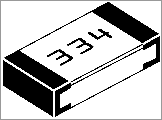 First two digits: two digits in the value.
Third digit: number of zeros after the first to digits.
334 = [33][0000] = 330k ohms
440 = [44][] = 44 ohms (not 440, the zero means zero zeros!)
000 = link (no resistance)
Monday, February 21, 2011

A great solder project
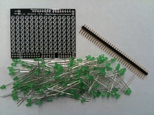
Need a good project for learning to solder things to boards? This is the one for you! These docs are great.
Sparkfun sells it here: http://www.sparkfun.com/products/9795
Connector Mania: JST-RCY
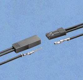
This is the connector that comes on small Turnigy batteries. Need to see if their discharge rates correspond to the specs below.
Note: many people mistake the gender of the connectors. The "real" gender is determined by the metal part. The big square plastic part that many people call the female actually contains the two male connectors.
Current rating: MAX 3A, Voltage rating MAX 250V
"The RCY connector is a compact, 2.5mm pitch wire-to-wire connector for use with a variety of circuits, from signal circuits to power supply circuits, in electrical equipment which is becoming more and more compact. The employment of a free spring contact method ensures stable contact performance, and superb working efficiency of insertion and removal."
PDF Specs
F1D - How One Gets Built

Do you love incredibly beautiful planes, have Faberge-egg level building skills, and are clinically insane? F1D might be for you! Check out the amazing shots of building 1 gram planes.
"For those not familiar with this type of indoor endurance model let me give a brief description here. The term 'F1d' refers to the FAI rule category. I don't have the rule book in front of me, but basically the models weigh in at minimum of 1 gram and a maximum of 2 grams. The wingspans are 65cm, or 25-1/2', long and a chord of 8' to 10'. The propellors are 20' to 24' inches in diameter. The flying surfaces and the propellor are covered with 'microfilm', which will be described later. The motor stick is a hollow tube of rolled balsa, and the model is braced with a superfine tungsten wire or kevlar fiber. Some competitors have developed spring mechanisms operated by the torque of the rubber band motors to effect variable pitch propellors!
World Championships are held every 2 years. Flights approaching 50 minutes are required to be competitive. The Kibbie Dome at the University of Idaho, in Moscow, Idaho, is one of the favored US flying sites and is pictured below. The balloons dotting the photo are used to steer the models at altitude in the event they are drifting into hazard. There are several models aloft in this picture, but due to their transparent covering and almost non-existent structure they are nearly invisible.?
Balls of Steel -- FPV Fireworks edition

From the FPV-Cordoba team. unedited video here:
http://fpv-cba.com.ar/fpv2
Sunday, February 20, 2011
Free Flight at Concord Model Engineers Fun Fly
Apropos of the Float movie, here are a couple of quick videos I took at the Concord Model Engineers fun fly.
Float Documentary

We have some free-flight guys at the Concord Model Engineers. Some videos here:
http://eastbay-rc.blogspot.com/2011/02/free-flight-at-concord-model-engineers.html
It looks like there's a different cut of the trailer here:
http://www.wimp.com/rubberplanes/
Update:
Funded via KickStarter! with another trailer cut.
http://www.kickstarter.com/projects/bensaks/float-a-documentary-capturing-the-art-of-flying
Saturday, February 19, 2011


Thursday, February 17, 2011
howto: bind a transmitter and receiver
Procedure
- power off receiver
- power off transmiter
- insert bind plug onto BAT pins
- actually, I think it can go on to any pin
- orientation doesn't matter, it just connect out neutral and control pins - power on receiver
- light will blink - put transmitter throttle to zero position
- toggle and hold bind switch on transmitter
- power on transmitter
- hold until binding is made
- usually just a couple of seconds
- plugging in servo, power connections into receiver backwards
- turning on transmitter first
- plugging in servo, power connections to wrong terminals
Crimping Connectors
Deluxe Crimping Tool:
Chris Hansen has written the most amazing guide to crimping, servo connectors, and JST connectors I've seen. He's like the Beethoven of crimping and connectors!
The link above points to his really excellent crimping tool. Crimp kits (what I've bought... be sure and get a wire stripper if you don't have one for the tiny gauge wire) are here.
He's got a splendid guide, A Brief Discourse on Connector Antics (pdf). I wish there were this level of detail on everything in RC land!
"This is the best crimping tool we've ever used for making servo connectors. The ratcheting hinge lets you lock in the terminal first, then insert the wire. This tool gives you a lot of leverage so every crimp is extremely strong, but is comfortable and easy on the hands even after a lot of use. If you're going to be making a lot of connectors then this tool is well worth the investment - take a look at the comments below. Tools of this quality usually cost over a hundred dollars."
Chris Hansen has written the most amazing guide to crimping, servo connectors, and JST connectors I've seen. He's like the Beethoven of crimping and connectors!
The link above points to his really excellent crimping tool. Crimp kits (what I've bought... be sure and get a wire stripper if you don't have one for the tiny gauge wire) are here.
He's got a splendid guide, A Brief Discourse on Connector Antics (pdf). I wish there were this level of detail on everything in RC land!
"This is the best crimping tool we've ever used for making servo connectors. The ratcheting hinge lets you lock in the terminal first, then insert the wire. This tool gives you a lot of leverage so every crimp is extremely strong, but is comfortable and easy on the hands even after a lot of use. If you're going to be making a lot of connectors then this tool is well worth the investment - take a look at the comments below. Tools of this quality usually cost over a hundred dollars."
Wednesday, February 16, 2011
Let There Be Light (Emitting Diodes)!
Here's how we attached LED lights to Arcticopter 1.
 LED strip lights are pretty amazing things. They're thin, have LEDs mounted on flexible strips with which carry the current, and have sticky backing. We bought four colors: red and green for left and right (as per standard aviation habit), white for front, and blue for the rear. They come in 1 meter strips, and can be cut every 5 cm (every third LED) to make the length you need.
 Here's the shopping list:
 There are two different kinds of light strips -- waterproof and non-waterproof. For aeronautical purposes, get the non-waterproof, they are a lot lighter... 12 grams vs 36 grams per meter. Unless of course, you're making an amphibious flying vehicle!

 The current draw for four 1-meter strips is 0.1, 0.4, and 1.1 amps at 11.4 volts at min, half, and full power (unscientifically measured by my turning the knob on my servo tester -- more on hooking things up below). I haven't measured with smaller strips, but I think the current draw will be smaller in proportion to the number of LEDs being driven.
 Here are the two kinds of strips. Note that every 5cm there's a "cut here" spot. The waterproof strip has a nice scissors marking to leave no doubt.
 On the far left of this photo, we can see there's a built-in resistor; we don't have to worry that we'll burn out the LEDs. In the middle we see the cut line. On either side of the line, we see the solder pads.

 Here are side views of each of the normal and waterproof strips. You can see there's lots of plastic encasing the waterproof strip. Both have 3M sticky backing.
Wiring the Strips -- First Try
Here are side views of each of the normal and waterproof strips. You can see there's lots of plastic encasing the waterproof strip. Both have 3M sticky backing.
Wiring the Strips -- First Try
Here's my first try at wiring the strips. I used some JST-RCY connectors (with leads: male and female) that I had laying around. It works, but I think it can be better -- lighter, smaller connectors, and with less wire clutter. See below for a second try.
 The arms are about a foot long -- a 15-light, 25cm strip will fit perfectly.
 I cut 2 each 25cm strips of the four colors: red, green, white, and blue. Some of the strips had the original wires attached; Since we want all the strips to be consistent in the wire length, we'll desolder those.
Soldering the Strips
[placeholder for LHS pic] I'll add some pictures later of the soldering. For now, I'll just note that I had some JST-RCY connectors attached to leads, and soldered those to the strips. The small circles next to the cut lines are solder pads.
Strip your wires to about 2mm, tin them, tin the solder pads with a blob of solder, and then "mash" the tinned wire into the solder blob. It will melt almost immediately and make a nice looking connection with your wire in the middle. When you tin the solder pads, there will be a thin covering film that will evaporate off and expose the pad. If you don't get a nice circular blob, try again.
If you're working with the waterproof strips, use an Exacto blade and push it straight down through the plastic. You can then lift the plastic off of the strip. Get as much of the plastic off as you can... you can melt through it with the soldering iron, but it's probably made of stuff you don't want to be inhaling a lot of.
Note that LEDs have polarity, and the strips do as well. Before you desolder the supplied wires, note which sides are attached to the hot and neutral wires. After you solder each pair of wires, stick them onto a convenient 2S or 3S battery -- if the strip doesn't light up, you've got the wires backwards -- desolder them and try again.
 Here's the power harness I wired up... Eight female (note discrepancy of terminology) JST-RCY leads for each of the strips, and a male JST lead to plug into the wired ESC output (or to a battery, if you're skipping the ESC). It's heavy, and bulky when stuck into the frame, but it works. I soldered a female JST-RCY onto the ESC output leads.
 Here's everything connected together and attached to a 3S battery. You can use a 2S battery if you want it dimmer, but it seems most people like the brightness from the 3S. I've got the ESC attached to a servo tester. If you don't have one you can connect to a receiver and control with your transmitter, but you really should consider getting one -- it's cheap and saves you a lot of time at the workbench.
 I used 8mm shrinkwrap to wrap the end of the strip. It doesn't seal up tight on the wire end, but it does do a good job of strain relief. If you know of a better way (funnel-shaped shrinkwrap?) please drop me a line!
Wiring the ESC
Wiring the ESC is pretty simple. Put your favorite battery connector on the battery end. If you don't have a favorite, the JST-RCY is small. That's what I will be using. On the other end, put whatever connector you've used to wire up your lighting harness. For my first try, that was a JST-RCY. For the second attempt, I'll try using a universal servo connector if the current isn't too much -- I don't think it will be.
Another option is powering the strips directly. It will work (because of the built-in resistors), but may give you much brighter lights than you want. This is especially important if it's dark, since they may clobber your night vision. Perhaps this could be controlled with resistors?
Wiring the Strips -- Second Try
coming...
Attaching the LED strips
 Attaching the strips was pretty straightforward. I used blue tape to position everything temporarily to make sure everything fit.
 I wrapped the inside wire for strain relief. You can see the big clump of wires below, and why I want to rewire this.
 Here's everything attached and turned on. I'm hoping that it will be plenty bright for daytime use. It's sure bright sitting on my dining room table!


 Here's the shopping list:
- - LED strips (non-waterproof): Red, Green, White, Blue
- - Brushed ESC
- - Connectors
- - Wago Connectors -- these are great for temporary wiring, since it can hold five wires together and the snaps allow wires to be added and removed individually.
 There are two different kinds of light strips -- waterproof and non-waterproof. For aeronautical purposes, get the non-waterproof, they are a lot lighter... 12 grams vs 36 grams per meter. Unless of course, you're making an amphibious flying vehicle!
 The current draw for four 1-meter strips is 0.1, 0.4, and 1.1 amps at 11.4 volts at min, half, and full power (unscientifically measured by my turning the knob on my servo tester -- more on hooking things up below). I haven't measured with smaller strips, but I think the current draw will be smaller in proportion to the number of LEDs being driven.
 Here are the two kinds of strips. Note that every 5cm there's a "cut here" spot. The waterproof strip has a nice scissors marking to leave no doubt.
 On the far left of this photo, we can see there's a built-in resistor; we don't have to worry that we'll burn out the LEDs. In the middle we see the cut line. On either side of the line, we see the solder pads.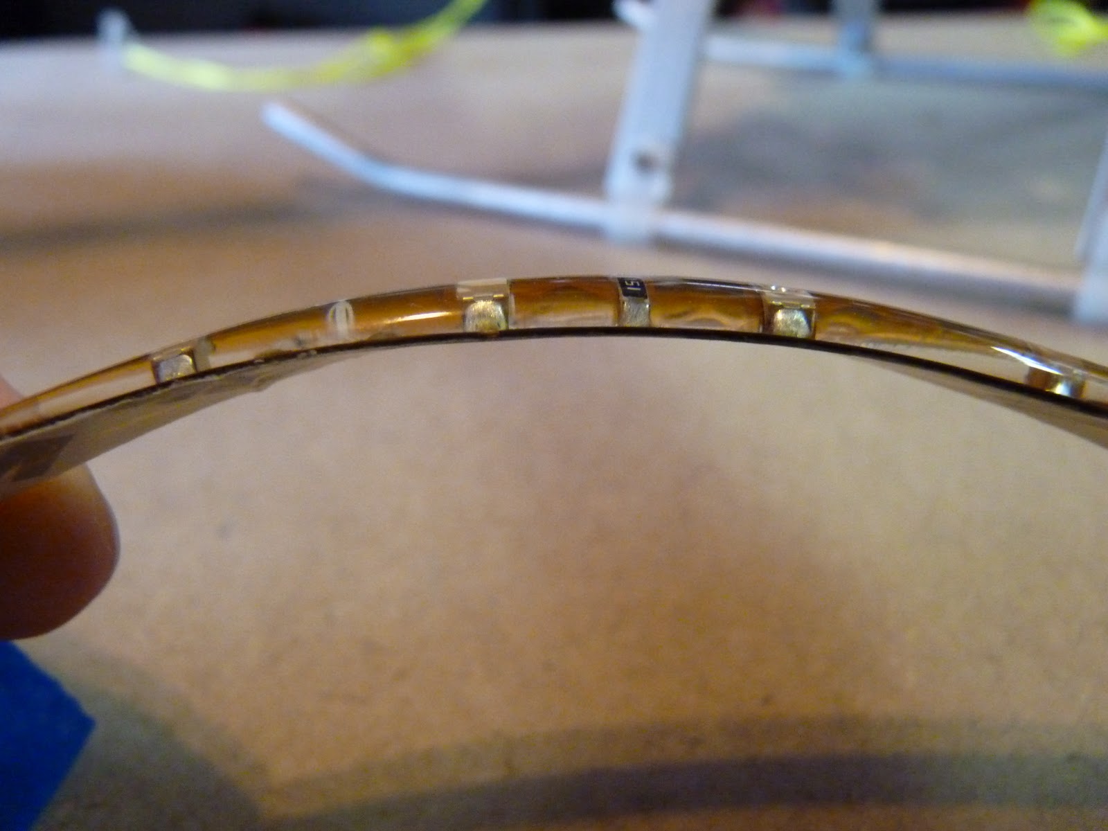
 Here are side views of each of the normal and waterproof strips. You can see there's lots of plastic encasing the waterproof strip. Both have 3M sticky backing.
Here's my first try at wiring the strips. I used some JST-RCY connectors (with leads: male and female) that I had laying around. It works, but I think it can be better -- lighter, smaller connectors, and with less wire clutter. See below for a second try.

 I cut 2 each 25cm strips of the four colors: red, green, white, and blue. Some of the strips had the original wires attached; Since we want all the strips to be consistent in the wire length, we'll desolder those.
Soldering the Strips
[placeholder for LHS pic] I'll add some pictures later of the soldering. For now, I'll just note that I had some JST-RCY connectors attached to leads, and soldered those to the strips. The small circles next to the cut lines are solder pads.
Strip your wires to about 2mm, tin them, tin the solder pads with a blob of solder, and then "mash" the tinned wire into the solder blob. It will melt almost immediately and make a nice looking connection with your wire in the middle. When you tin the solder pads, there will be a thin covering film that will evaporate off and expose the pad. If you don't get a nice circular blob, try again.
If you're working with the waterproof strips, use an Exacto blade and push it straight down through the plastic. You can then lift the plastic off of the strip. Get as much of the plastic off as you can... you can melt through it with the soldering iron, but it's probably made of stuff you don't want to be inhaling a lot of.
Note that LEDs have polarity, and the strips do as well. Before you desolder the supplied wires, note which sides are attached to the hot and neutral wires. After you solder each pair of wires, stick them onto a convenient 2S or 3S battery -- if the strip doesn't light up, you've got the wires backwards -- desolder them and try again.
 Here's the power harness I wired up... Eight female (note discrepancy of terminology) JST-RCY leads for each of the strips, and a male JST lead to plug into the wired ESC output (or to a battery, if you're skipping the ESC). It's heavy, and bulky when stuck into the frame, but it works. I soldered a female JST-RCY onto the ESC output leads.
 Here's everything connected together and attached to a 3S battery. You can use a 2S battery if you want it dimmer, but it seems most people like the brightness from the 3S. I've got the ESC attached to a servo tester. If you don't have one you can connect to a receiver and control with your transmitter, but you really should consider getting one -- it's cheap and saves you a lot of time at the workbench.
 I used 8mm shrinkwrap to wrap the end of the strip. It doesn't seal up tight on the wire end, but it does do a good job of strain relief. If you know of a better way (funnel-shaped shrinkwrap?) please drop me a line!
Wiring the ESC
Wiring the ESC is pretty simple. Put your favorite battery connector on the battery end. If you don't have a favorite, the JST-RCY is small. That's what I will be using. On the other end, put whatever connector you've used to wire up your lighting harness. For my first try, that was a JST-RCY. For the second attempt, I'll try using a universal servo connector if the current isn't too much -- I don't think it will be.
Another option is powering the strips directly. It will work (because of the built-in resistors), but may give you much brighter lights than you want. This is especially important if it's dark, since they may clobber your night vision. Perhaps this could be controlled with resistors?
Wiring the Strips -- Second Try
coming...
Attaching the LED strips
 Attaching the strips was pretty straightforward. I used blue tape to position everything temporarily to make sure everything fit.
 I wrapped the inside wire for strain relief. You can see the big clump of wires below, and why I want to rewire this.
 Here's everything attached and turned on. I'm hoping that it will be plenty bright for daytime use. It's sure bright sitting on my dining room table!
Subscribe to:
Posts (Atom)