Showing posts with label soldering. Show all posts

Wednesday, July 30, 2014

Soldering: Some Through-hole Counterexamples

 Here's the first row of pins by a beginning student.  Note that the plating on this board is pretty minimal.
Problem: Incomplete solder joint on D, E.
Cause: not enough solder fed into the joint.
Solution: Feed enough solder to make a nice Hershey's Kiss shape.
Problem: Middle joint flows into adjoining through-hole.
Cause: Too much solder, or soldering iron crossing two holes.
Solution: Make sure your iron is firmly contacting just one hole/pin, and don't feed too much solder.


After just a couple of rows, the joints are good, and look like Hershey's Kisses.


Problem: "Mushroom" Top, no connection to through-hole.  Look at the third from the right.
Cause: Not making contact between the through-hole and the soldering iron.  The plating is pretty minimal -- this is more symptomatic of Cheap PC board construction.  In our previous class we had some higher quality boards and didn't see this problem.
Solution: Bear down on the iron, to make sure there's a good concurrent touch between the pin and the through-hole.

And here's the same board, after cleanup.  Textbook job!  If you have a wedge or screwdriver tip, be sure the flat edge is touching both the pin and the pad.


blogodex = {"toc" : ["Soldering", "Soldering Class"]};

Monday, July 7, 2014

EastBay RC Guide to Soldering

Overview.

This are the notes and videos for a two-hour introductory soldering class.  It's designed to be taken Khan Academy style -- watch the videos and read the notes first, and we'll be able to spend the entire class on soldering.
  • Hands-on class, two hours.
  • Time: 15 minutes, intro and tinning soldering iron; 15 minutes, tinning wire; 15 minutes, soldering thicker wires; 10 minutes, soldering thinner wires; 30 minutes, soldering PCB; 10 minutes, heat shrink; 15 minutes, soldering pads.
  • Watch the videos first, be ready to practice in class.
EastBay RC is a continuing work in progress. Let me know what you think!

Here's all the videos as a playlist.  Watch it in HD, it will be a lot clearer.  I'm trying to figure out how to specify that an entire playlist should be shown in HD.  If you know how to do this, let me know! Individual videos are down below.


EastBay RC Soldering Class Notes, Coming Soon!

So I'm getting ready to teach a soldering class, and I thought it would be neat to do it Khan Academy Style.  So I'm prepping a couple of videos that cover the actual content, and the entire two-hour class will be devoted to soldering practice.

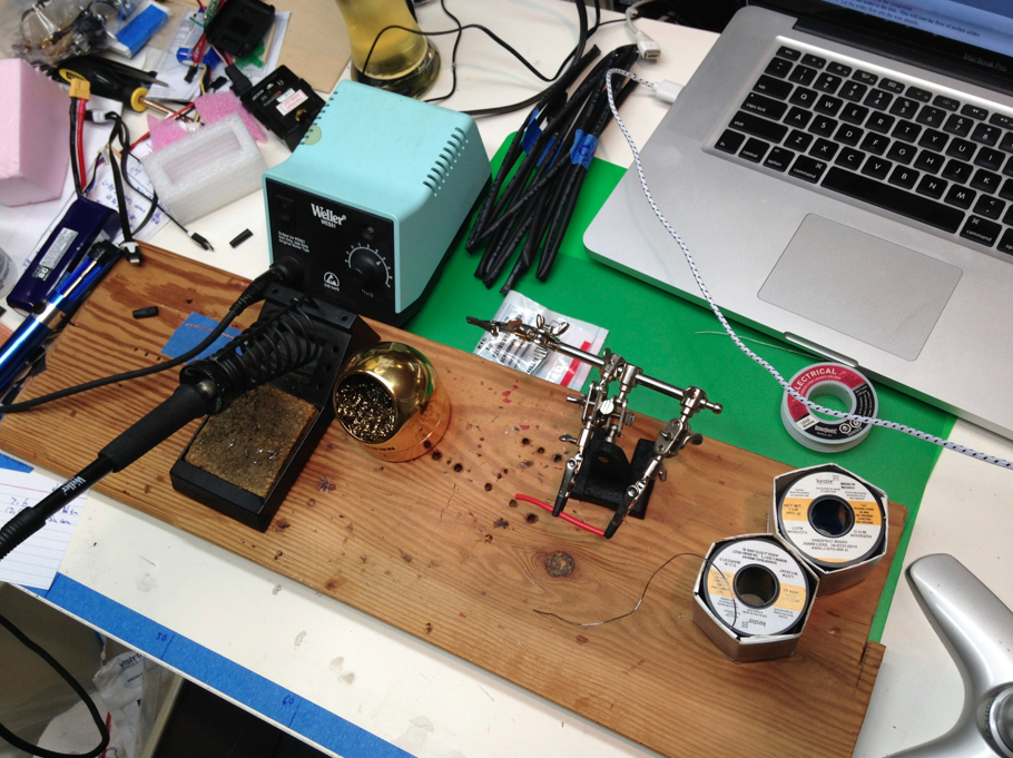
I'll have the content uploaded in the next couple of days.  I'd be interested in knowing what you think.  Until then, here's a preview of the Official East Bay Soldering Station!

blogodex = {"idx" : "soldering"};

Wednesday, June 12, 2013

Small Scale Battery Soldering

 The battery died in my tiny DSO Oscilloscope.  Opening it up showed a 1S LiPo of undetermined amperage.  Pay close attention to the smallness of the battery wires!
I had a spare 1S battery.  It was fitted with a JST connector, so I snipped that off.  The wires were huge compared to the old battery.

I'm pleased to say I got it soldered with no problem.  It's the closest work I've ever done with a live battery and I'm happy to say nothing was shorted. I was really sweating it out though!

I'm putting this picture up partly as reference for battery orientation, and partly coz I'm pleased with being able to make this connection successfully.

Saturday, October 27, 2012

Soldering Notes

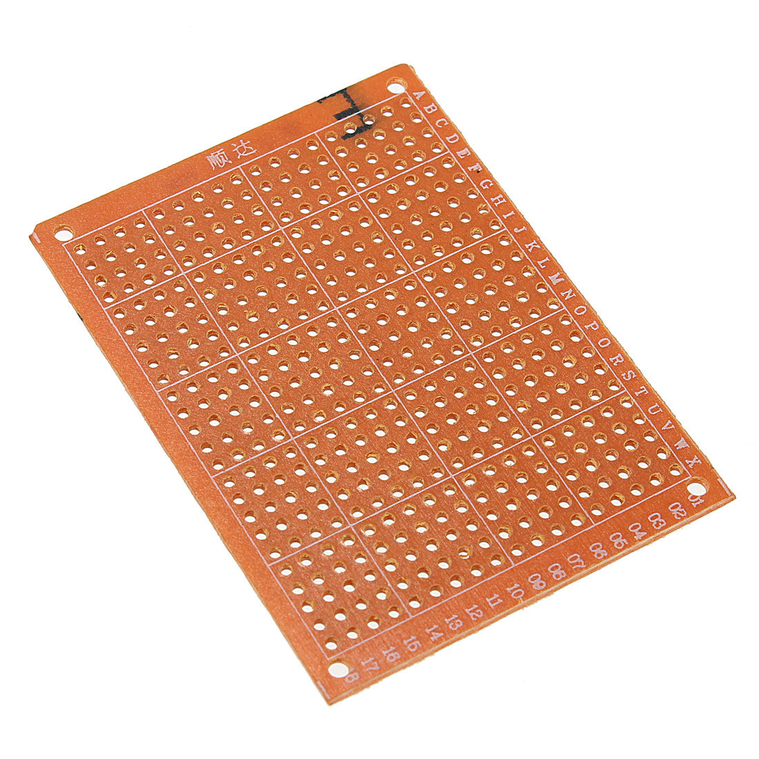
Here's how I practiced my soldering.  I got some printed circuit boards and a bag of headers, and soldered 725 through-hole connections.  It took me a couple of evenings (not working very hard) and when I was finished I felt pretty confident in my soldering abilities.


These 5x7 cm prototyping boards from banggood are less than a dollar, including shipping.

Sunday, December 4, 2011

My SparkFun Signature Edition Solder Fan

 So after looking around for some fans for a solder fume extractor, I came across some old PCs being recycled. I took out one of the PC cooling fans and tried that... it worked so well that it would scoot across the table under its own power!  So, I opened up one of the power supplies and removed the fan... it seems like the perfect size for a benchtop solder fan.  I hotglued it onto a piece of cardboard I cut out of an old SparkFun box I had sitting around.  Instant class and DIY cred at no extra charge!
For power, I attached a JST-RCY connector so I could power i from one of the small LiPo batteries I keep on my bench.  The fan uses .5A, so the battery in the picture will keep the fan going for two hours without problem. I measured this with my watt meter.  If you are doing anything with RC or motors you should have one.

If I would have had a spare 3-pin or 4-pin JST-XH I would have used that, so that it could have been powered off of any battery's balance port.

Here it is in action, shot with genuine shakycam:


Sunday, October 9, 2011

cheap lightweight battery for Night Vapor

 One of the things I love so much about my night vapor is how light and floaty it is.  Turn the throttle down, you can't hear the motor, and it just effortlessly glides across the room.

Of course, a lot of this is due to its light weight.  17g AUW with the supplied 70 mAh battery.  Unfortunately, extras of this battery are $5.50 + shipping, and when I originally ordered I think it was closer to $8.00!  So of course, everybody buys the cheaper, larger batteries.
 But, that adds another 2-3 grams to the AUW.  Still it's a fine flyer, but just a little bit more speed is necessary to keep it in the air, and just a bit of the floatiness is lost.  I can compare this out the Concord Model Engineer's indoor fun fly, where a couple of other guys have night vapors.

So, when I noticed that Hobby King had cheap single battery cells, I thought I would try to make my own.
 Here's exactly what I used:

Total cost for 3 batteries: $5.50, $1.82 each.

I've never worked with raw battery cells before, so I was a bit nervous.  It turned out to be no problem... just keep in mind that you're working with a live circuit, don't touch wires together, don't short the tabs with a screwdriver etc.

The battery tabs take standard solder.  I snipped and tinned my wire, and then tinned the battery tab, leaving a proper sized blob to attach the wire.
I then put the cell flat on a piece of wood, and lined the wire up.  Touching the soldering iron to the wire allowed me to mash the wire down onto the tinned tab, making a very nice solder joint.

On two of the cells I make a straight solder joint, so I had the shrink tube on the wire as I soldered it.  Because of this, the wires were a bit longer than I liked... extra weight, and I was worried it might not fit in the plane very well.
 So for the third try, I flipped the wire around.  This is the top battery in the first picture.  This produced excellent results:  the wire was a lot shorter, it ran alongside the battery, and I was able to put the shrink tube on after the soldering, since I could just slip it over the tab and wire, heat it, and trim.

I think I'll resolder the other two cells in the same way.


[update: solved the charger problem using the 1S extension wires from Hobby King.]

 Mini Plug Extention for Micro Battery 10cm (5pcs/bag)

 When soldering, be sure and do one side completely (all the way up to shrink tubing), and you'll have a lot less chance of shorting the battery tabs together.

The completed battery is too fat to to fit nicely in the holder, but a bit of blue tape holds in on nicely.  I might a a tiny bit of velcro as well.  When I flew it for testing, there was a bit more tape than what I'm showing here.
The batteries fly perfectly; slow and floaty behavior restored due to the low weight, and the 20S discharge gives a lot more power.  The original 70mAh cells don't have a discharge rating, but the replacement eFlight 150s are rated at 12C.

I didn't test relative flight times, coz I was pushing the testing between a couple of other activities.  I'm guessing it will be comparable to the original battery, but I'll try it later and update this post.


I've misplaced my little subgram scale, but using my big scale show the following weights:

  • Turnigy 138, 5g
  • Parkzone 150, 4g
  • Original Parkzone 70, 2g
  • These replacements, 2g (I'm assuming the 3rd one was a bit less and would show it on the higher precision scale)
But, using my big scale, the the plane's AUW including the battery drops from 17g to 16g (with no battery, it's 14g).  So, it seems that these replacements are lighter than the original, and could get even a bit lighter if I were more aggressive about trimming the wire.

They fit on the charger nicely... line them up and poke them in with your fingernail,  pull them out by holding on to both wires (not the battery body) when finished.  Note that I have to tip up the third battery to get it to fit into the solder.  When I redo the others, I'll solder on the other side of the battery (if possible?) so that the batteries won't have to be tipped up; but it doesn't seem to be enough of a problem to resolder the one that's already made.

Update: Figured out how to eliminate the shrink wrap.
http://eastbay-rc.blogspot.com/2012/01/update-night-vapor-batteries.html


Monday, February 21, 2011

A great solder project

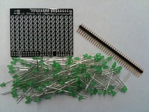
Make the LoL Shield

Need a good project for learning to solder things to boards? This is the one for you!  These docs are great.

Sparkfun sells it here: http://www.sparkfun.com/products/9795

Monday, February 14, 2011

Extending the motor wires

I made a mistake prepping the motor wires with the 3mm bullet connectors.  Unlike a plane (which I am used to), the motors on a quad sit quite a ways away from the ESCs.  So, when I went to wire everything up, there was a several inch gap between the connections.

So, I stripped the shrinkwrap and unsoldered the bullet connectors, and extended the wires.  There were a dozen of the things to do, so I did one first to check for fit, and then did the remainder in a batch, assembly-line style.  I made them a tiny bit longer than they needed, so that we would have some wiggle-room (literally) for the ESCs.  Next time, I'll try making it an exact fit.

I didn't try reusing the bullet connectors... they were kinda messy on the outside after soldering.  I wonder if there's any way to clean solder of lots of pieces at once?  I was also surprised at how heavy a dozen connectors full of lead solder weigh.  I tried using the minimum possible solder on the new connectors.  It made it a bit more tidy as well.  It seems just as strong... I wasn't able to pull it off by tugging at it.

I took photos... partly because I thought it might be useful for someone not super-experienced with solder, but mostly because I thought they would look pretty cool.

Cut all the wires to the desired length, strip and tin the bullet side.  You don't need much solder, since these are being placed in the connector cup. Just make sure the wires are saturated.  One of the previous posts has some details about using the board to hold the connectors.  Strip the insulation so that the exposed wire is just as long as the internal connector cup.

 Nicely attached to the connectors.  I was careful not to get any solder on the outside, which allows 3.5mm shrinkwrap to fit right over the connector.
3.5mm Shrinkwrap on the bullet connectors, ready for the heat gun
Nice looking shrink wrap job, huh?
 Now strip and twist the ends that will be connected to the motor leads.  It will be stripped a bit longer than the connector side, since this will be a wire-to-wire connection.
 Tin the wires.  Notice that we add a bit more of a solder blob (but still not too much; we don't want a big ball of solder in the middle of our wire).  We do the same thing to the motor leads as well.  When the wires are joined, the two solder blobs will be what flows between the wires.  Dont forget to add the shrink wrap before you solder, or you will have to unsolder and do it all again.  On the other hand, maybe that's good practice!
 Here's a set of wires soldered together...
 ... and shrinkwrapped.  Get a heat gun, it really does make a nicer looking connection than using a lighter or any other ghetto method.
 There are tons of techniques for soldering wires together, you can find some really great tutorials on youtube.  I like using an alligator clip to hold the two wires together.  When you heat the wires up, the solder melts, and the jaws of the alligator clip mash the two wires together nicely.

If the solder sticks to the alligator clip, touch the soldering iron to the outside of the clip and it will come right off.  Don't tug, or the two wires will come apart.
 Here's the finished set of motor wire extensions.  Doing them assembly-line style speeds things up a lot and reduces errors.  I wasn't looking forward to doing this, but it wasn't bad at all.  Maybe I'm just getting a bit more used to soldering as well.
Here's the finished result, held in place with blue tape.  Note the extra bit of slack... next time, I'll mount the ESC in its permanent position and try to do it so there's no slack at all.  And by "no slack", I mean "just enough slack so there's no strain on the connections".