Picking up the build the next day.
We used an extra platter to keep the wiring together. We used four extra standoffs (is that what these things are called?) Here's some notes about how they're attached.
The tabs have been trimmed from two of the standoffs, so that they're acting as spacers but don't need to be attached to the platter. this makes it easier to set up and remove.
Note that we cut off the tabs on two of the standoffs. Originally we did this because they were two-tab standoffs lining up with three-tab holes, but it turned out to be a very nice setup.
We filed out the tab holes on the top platter so that it seats and unseats smoothly. We'll use some thin bolts to hold things together.
We'll try putting another platter on top (or below?) to cover up the stabilization board.
The standoffs are placed in the holes that are offset from the arms, allowing unobstructed access for the wiring.
We got lucky... the motor wiring, the ESC wiring, and the Wago connectors were the perfect size so that everything fit without having to add any extra wir

The KKBoard is being moved between the Arcticopters 1, 2, and (soon) 3 until some more boards arrive, so it's attached to a carrier board.
The KKBoard is sitting on a double layer of 3M doublesided foam tape, and attached to the carrier with zip ties.

For now we've got everything taped together, but we'll figure out how to attach it so that it's stable, firm, and easy to move.

HINT: don't mess up and mount your board at 90 degrees to what it should be. As soon as you apply the smallest amount of power it will attempt to correct itself by instantly flipping upside down!

We didn't have a lot of luck with the music wire legs... Since the weight should not be an issue with the motors we've got, we tried zip-tying wiffle balls under the motors. The motor mounts make a natural cradle that holds it in place. Use some pliers to pull the zip tie tight and it's very stable. This worked pretty well. I'll get some numbers on the wiffle ball weight.
I'll try the music wire legs on Arcticopter III which will be much smaller and as light as I can get it.
A KFC bowl is the perfect size for covering the platter. Thanks Colonel, this flight's for you!

Flight videos in the next post!
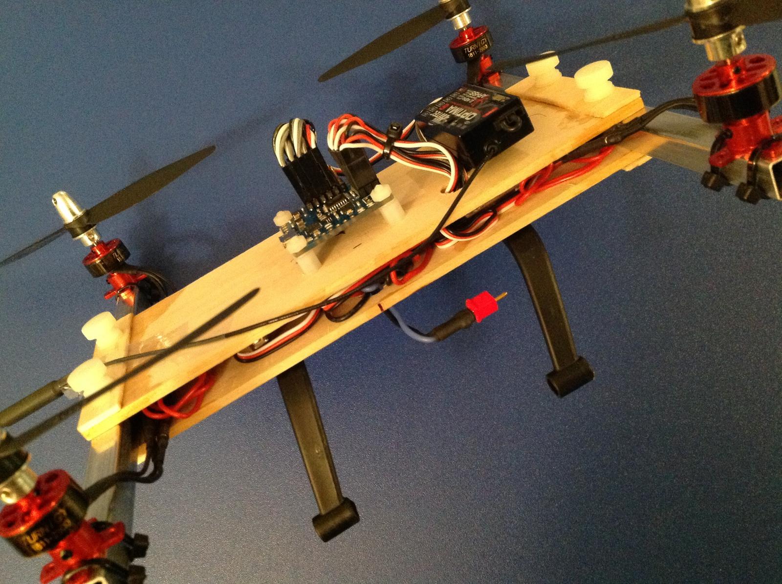


 The KKBoard is being moved between the Arcticopters 1, 2, and (soon) 3 until some more boards arrive, so it's attached to a carrier board.
 For now we've got everything taped together, but we'll figure out how to attach it so that it's stable, firm, and easy to move.
 HINT: don't mess up and mount your board at 90 degrees to what it should be. As soon as you apply the smallest amount of power it will attempt to correct itself by instantly flipping upside down!
 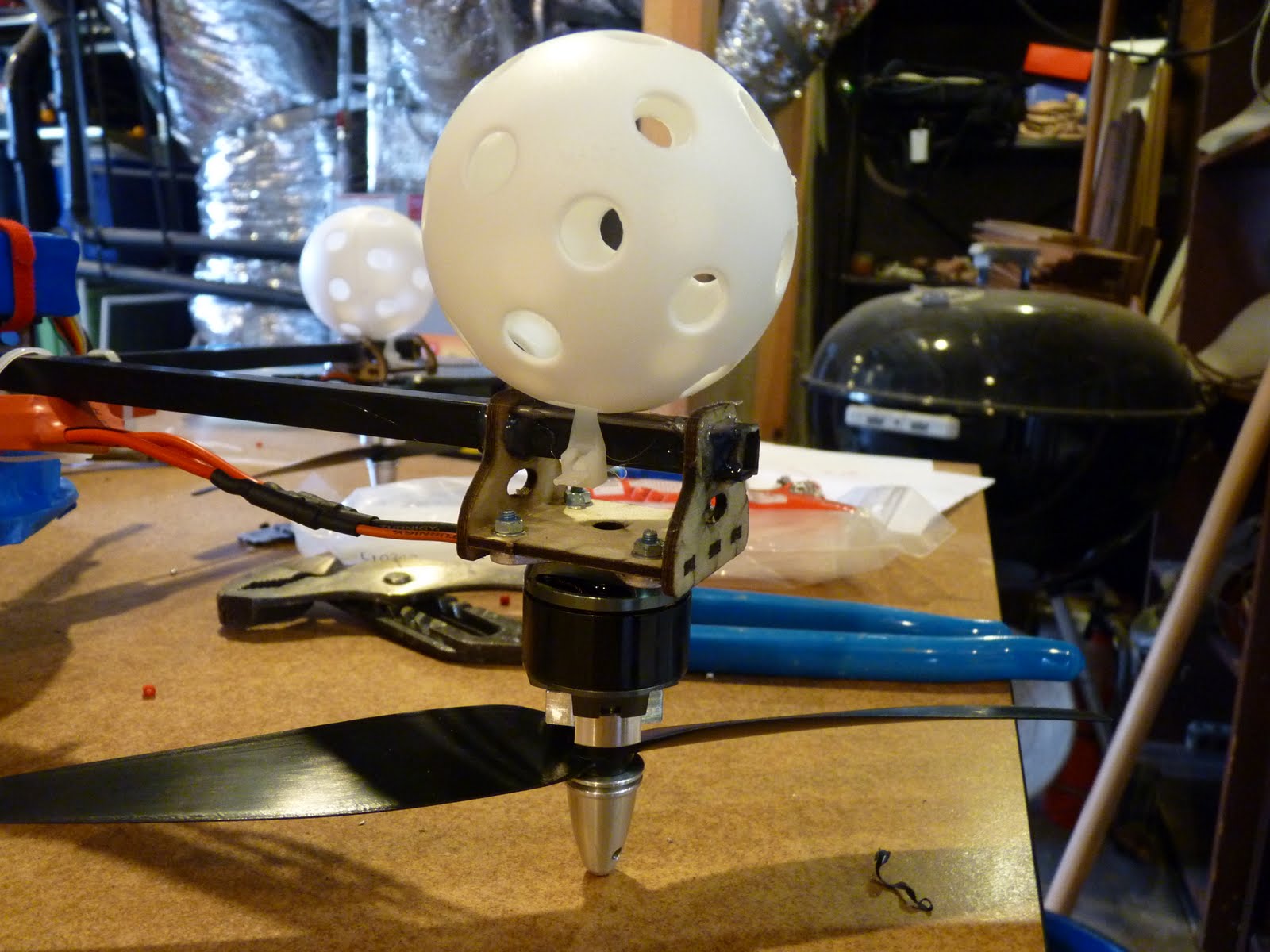 We didn't have a lot of luck with the music wire legs... Since the weight should not be an issue with the motors we've got, we tried zip-tying wiffle balls under the motors. The motor mounts make a natural cradle that holds it in place. Use some pliers to pull the zip tie tight and it's very stable. This worked pretty well. I'll get some numbers on the wiffle ball weight.
 Flight videos in the next post!
 Here's the basic RadicalRC kit assembly. It's really nice. We're using the carbon fiber arms. Everything fit together nicely, and we glued it up with medium CA. Hot glue seems to be just fine to center the arms.
 Wago connectors for power distribution, as noted here. These have been great on the Arcticopter I. These motors are a lot bigger, so it will be interesting to see the power draw through the connector. The motors max out at 375 watts each, but this thing will be at airliner altitudes if you keep that much power for too long.
 Here's the basic frame with motors attached. It's very light and solid. I had originally been a bit skeptical about the 10mm arms but am now a big fan.
 The motor had an extended shaft. Drilling through the carbon fiber arm was a no-go, so Andreas tried every saw in his shop to cut off the motor shaft. None of them even scratched the shaft, which is why every RC toolbox should include an angle grinder with cutoff wheel.


 Here's how the motors are mounted. The bolts have "blue" removable threadlock.

 Say hello to our little 4S friend. One goal of Arcticopter II is to measure the payload size that can be reasonably handled. The final Arcticopter will need to carry Josh's full-sized Canon DSLR... we probably should find out the target weight.
 For some unknown reason, the Hobby King shipment did not include the expected fasteners. Fortunately the local Ace has a nice selection of metric fasteners. Judging by the price, they're made from an allow of platinum, iridium and gold.


