Showing posts with label technical. Show all posts
Sunday, June 5, 2011
Motor Math and Propeller Basics
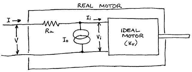
A couple of nice articles which were pointed out by Superfly maven Tram. It looks like there's a lot more interesting things there as well.
Friday, May 27, 2011
Elevon / V-Tail Mixing Calculations
update: moved this into its own post. original elevon description here.
a = x/2 - y/2
b = x/2 + y/2
where
Calculating Elevon Motion
There are two calculations, one for each elevon:
a = x/2 - y/2
b = x/2 + y/2
- a = left elevon deflection,
- b = right elevon deflection,
- x = aileron position (-1 = far left, 0 = centered, 1 = far right),
- y = elevator position (likewise, -1 .. 1)
Deriving the Elevon Calculation
I couldn't find the above formula anywhere on the web, probably because it's so obvious to everybody but me. Here's how I figured it out. Real mathematicians would do it much easier I'm sure!
First, look at the inputs and outputs. The above video shows the endpoints and midpoints of the two axes.
which gives us this table for the values of A and B:
a,b = f(x,y):
x=-1.0 x=0.0 x=1.0
y=1.0 -1.0, 0.0 -0.5, -0.5 0.0, -1.0
y=0.0 -0.5, 0.5 0.0, 0.0 0.5, -0.5
y=-1.0 0.0, 1.0 0.5, 0.5 1.0, 0.0
x=-1.0 x=0.0 x=1.0
y=1.0 -1.0, 0.0 -0.5, -0.5 0.0, -1.0
y=0.0 -0.5, 0.5 0.0, 0.0 0.5, -0.5
y=-1.0 0.0, 1.0 0.5, 0.5 1.0, 0.0
Showing only the values for A, we notice that there's a pattern across the rows, namely that it increments by .5 each row, as X varies from -1 to 1. So, we can start with "+ x/2" for each of the rows, for some value of Y.
a = f(x,y):
-1.0 -0.5 0.0
-0.5 0.0 0.5
0.0 0.5 1.0
-1.0 -0.5 0.0
-0.5 0.0 0.5
0.0 0.5 1.0
Likewise, we can see the same pattern for the columns in the other direction. Fiddling a bit, I came up with -y/2 + x/2 which of course simplifies to x/2 - y/2. I guessed there was a similar pattern for B, and tried a few variations of adding and subtracting x/2 and y/2. until I confirmed that x/2 + y/2 worked.
Here's a bit of python that reproduces the table above:
for x in (-1.0, 0.0, 1.0):
for y in (1.0, 0.0, -1.0):
a = x/2 - y/2
b = x/2 + y/2
print a,
print b,'\t\t',
print
for y in (1.0, 0.0, -1.0):
a = x/2 - y/2
b = x/2 + y/2
print a,
print b,'\t\t',
Friday, October 1, 2010
Notes on prop pitch
Great write-up by Gordon Johnson:
http://www.rcgroups.com/forums/showpost.php?p=16189250&postcount=4
Sunday, September 26, 2010
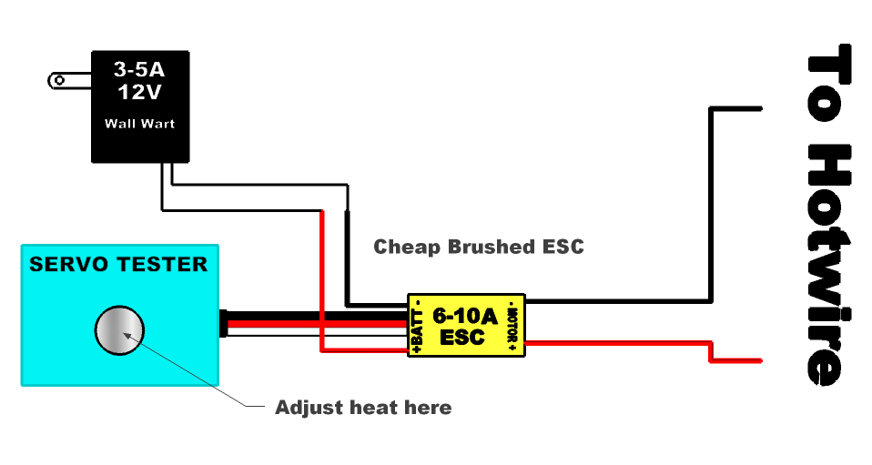
Simply Brilliant Hot Wire Cutter Power Supply
From user 7up on rcgroups. Power from a 3-5A 12V wall wart, managed by a 6-10A brushed ESC, controlled by a servo tester. Attach the hotwire to the motor wires.Saturday, September 25, 2010

A nice explanation of PPM radio signals
http://www.mftech.de/ppm_en.htm
Interestingly, the radio transmitter and receiverr does no transformation of the signal between the encoder and the servo.
Tuesday, August 10, 2010
Monday, August 9, 2010
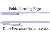
Kline-Fogelman airfoil thread
Here's the official RCGroups discussion thread for the Kline-Fogelman airfoil. With contributions by Dick Kline!
TxDuino -- controlling a Futaba transmitter via PC
Controlling a transmitter via PC.
PC -> USB -> Arduino -> PPM -> Futaba module -> receiver.
The TxDuino project aims to create a single device that allows a PC to control an RC vehicle. At the time of starting this project, the only option for doing this was a device from here that could be plugged into the trainer port of a transmitter. An arduino has been used to achieve this same setup as described here. Going through the handheld transmitter, however, is a huge hassle for a number of reasons so I set out to create a simple single device that could accomplish this. As it turns out, so did the guys at Tom’s RC, their solution being this guy here. Anyway, since the work is done, I’ll share the results.http://cheshirekow.com/blog/?p=236
Tuesday, August 3, 2010
Controlling Servos
Some servo-related linkage...
Bonus:
Bonus:
- Electric Motors 101 -- DC, AC, brushless, servo, stepper, more...
Thursday, July 29, 2010
HobbyKing Orange Micro DSM2 Receiver
- no instructions included (therefore, this post!)
- no problem with binding.
- works well.
- added 1.5" heatshrink myself.
- Pin assignment are the same as the AR6110e.
- Wire attachments are OPPOSITE the AR6110e. Control line is on the TOP.
Two chips on board:
- left chip is covered with glue, anybody know what it is?
- right chip is Cypress Semi CY8C21434 (datasheet).
Wednesday, July 14, 2010
How to replace a bind plug?
Freechip provides the answer:
If you have old servo leads or old servo extensions you can use these, strip and twist the 2 outer wires on the 3 wire lead and short them together.
The bind plug shorts the outer 2 pins on the BATT/BND port.
If you have a helping hand you can also use small needles nose pliers you can use them to short the 2 outer pins.
Monday, July 12, 2010
Subscribe to:
Posts (Atom)