Showing posts with label electronics. Show all posts

Tuesday, April 24, 2018

Stepper Motor: Microstepping

A coworker explains it to me:
TL;DR; is that instead of just having full forward/reverse current or not on each winding, the driver can also do things like 90%/10%, 80%/20%, 70/30, etc. current for the two windings to position the motors at angles between the full/half step positions. the actual ratios aren't quite this simplistic, and are designed to achieve something close to constant holding torque and even step spacing, but since the exact angle achieved for any winding current ratio depends on the motor design, and application, it's more or less impossible to get microstep positions that are a precise fraction of the full step angle for all motors/applications. this is mostly OK because 1) you're not making the full step positions any less accurate, 2) you're still making motor motion smoother by taking smaller steps.
a longer explanation can be found at https://hackaday.com/2016/08/29/how-accurate-is-microstepping-really/. if you want to go deeper that that, there are lots of motor controller app notes out there with all the gorey engineering details.

blogodex = {"idx" : ["electronics", "stepper motors", "microstepping"]};

Thursday, August 21, 2014

FTDI, VCC, and the Arduino Pro Mini

This project has been the first one where I've used a 3.3V Pro Mini.  There's some important things to keep in mind regarding power input.
  • Power input on RAW can be 3.3V - 12V.  It will be regulated to 3.3V.  Specifically, VCC will be 3.3V
  • Power input from the FTDI connector is not regulated. If you are using a 5V FTDI connector VCC will be 5V!
  • In general you can get by with using a 5V FTDI cable on a 3.3V Pro Mini.  It's out of spec but is generally accepted as working.
  • You can't use a 5V FTDI if you are powering a 3.3V device from VCC!

Here's a workaround if you're stuck with a 5V cable and want to use it to power a Mini that has a 3.3V device on VCC.


Remove the VCC line from the FTDI cable.  Gently lift the plastic tab and the  wire with attached connector will slide out.  If you have an extra single-ping cable protector (take one off a female-female breadboard wire if you've got one) you can insert the VCC connector in there.  You could also use some small heatshrink to cover it.  You could let it go bare, but be careful not to short it out.


Attach the FTDI cable (minus the removed VCC) to the Pro Mini as usual.  Attach FTDI VCC to Pro Mini RAW.

Check the voltage on Pro Mini VCC.  It should be 3.3V, regulated by the Pro Mini.


The Sparkfun product page has this note in the comments:

Q: Are the rx/tx lines 5V tolerant? I want to know if it is possible to program this with a 5V FTDI board, without needing to get an additional 3.3V FTDI just for this board. 
A: Yes, the only difference in the 3.3V and 5V Pro Minis is the crystal and the voltage regulator. Since the FTDI bypasses the regulator the only difference is the speed the run at. The ATMega328 is fine at 5V. Keep in mind if you have 3.3V on VCC and 5V on the I/O pins that is technically out of spec (you shouldn't put more than VCC on the I/O pins), but will probably work as well. Keep in mind that the 5V FTDI will put 5V on the VCC line, so make sure you don't have any 3.3V only devices connected when you do this.

blogodex = {"toc" = ["FTDI", "Arduino"], "idx" = {"ArrBot", "Electronics", "Voltage", "No Hack Too Cheap"]};

Sunday, July 7, 2013

SMD LED's Seem Quite Small...

 ... Until you get the bright idea to use SMD resistors to save weight! See the tiny white thing?  That's the LED.  And the little spec beside it, that's the resistor.  I had no idea they would be so small... it didn't occur to me that the ebay vendors would be photographing those things in such closeup.  I'm going to try to see if there's a larger size of SMD resistor.  Ideally I would be able to solder the resistor directly to the LED, forming one piece to mount.  BTW the white thing in the upper-left is the package of 50 resistors.
Here they are getting ready to be soldered.  It turns out that it's possible, but I didn't get any pictures of the soldering process, mainly because I wasn't optimistic enough to have a camera ready.  I'll follow up with some notes on how I did it and some pictures.

This is for adding some nav lights to the ladybird.  If there were some ready-made ones I think I would buy them without hesitation, but it's been educational learning how to deal with such tiny pieces.

Friday, September 21, 2012

SMD LED Sizes

Here's an illustration of the various sizes of SMD LEDs.  They're pretty cheap on ebay.  0603 Soldering tutorial.  Several more on youtube.  I'm trying to figure out what size is best for the Ladybird.

Note: on the back side there's an arrow. The arrow points to the negative wire.


Dimensions:


  • 0603. Footprint: 1.60 x 0.80 x 0.40mm.
  • 0805. Footprint: 2.00 x 1.25 x 0.80mm.
  • 1206. Footprint: 3.20 x 1.60 x 1.10mm.

This is the 1206 data from the ebay vendor:


Tuesday, January 24, 2012

Monday, January 16, 2012

SMT overview

Looks easier than I thought!

Adding MP3 to your project

A nice instructable for adding MP3 to your project for about $3.

Basic idea:

  • get a cheap MP3 player.  A Miniclip is about $3 on ebay.
  • open it up. remove the battery
  • power via your project
  • solder some wires to play and pause pads
  • set the output of these line high
  • to "push" the buttons, set the line low for a short time


Sunday, October 2, 2011

Monday, July 18, 2011

TJinGuy's great website

Here's a website with lots of nice technical details.  Especially interesting are his articles on charging and RC / battery wiring.  Check it out!  Here's a sample of one of his wiring diagrams:

Sunday, February 27, 2011

HowTo: Using a crimping tool, part 1

Here's how to use a crimping tool to make your own servo connections.  This can be useful to get an exact fit, and also saves you from having to keep around lots of servo wires or wait for servo wires of a particular length to be shipped.

Note that there are two kinds of servo connections: "JR" (also known as "Universal"), and "Futaba".  As the name suggests, JR is the most common type.

Note also that this is an area where people mess up the gender terminology.  Follow the metal, and not the plastic covers.  The large square plastic cover (which looks like it might be the female) actually holds the three male connectors.

 Here's two female connectors, one crimped and one out of the package.  That's a 22-gauge wire.  Note that there's two sets of crimp teeth, and both of them are in contact with stripped metal.  If you try to crimp over the insulation, you will chop the wire in half.
 Strip 5mm of the end of the wire.
If you don't have a tiny-gauge wire stripper, you can carefully strip it with an exacto blade.  After its stripped give the threads a twist to keep them together, but don't tin them.
 Here's the crimping tool.  Stick the connector into the gap of the crimper and line up the wire end with the jaw edges.  The gap in the connector should be facing up.  Note that we're looking at the gauge numbers on the jaws -- this is important, it won't work well if you reverse them.
 Close the crimping tool a couple of clicks, until the jaws just start to mash the connector.  This will hold the connector nice and tight, making the next steps easy.
 Put the wire in the hole in the connector.  Don't put any insulation in the hole.
 Once everything's lined up, squeeze the crimper to the last click.  The crimped metals are now bonded together.  Wires in real planes are required to be crimped rather than soldered, since soldering makes a hard joint that when vibrated can cause the wire to break.
 Open the jaws.  Remove the connector carefully by pulling on the wire.  Don't pull on the end of the connector... it's not very strong and will bend easily.  If you bend it too much it will break off.
Here's the flip side of the crimper.  Note that the jaw is slightly recessed to keep the end of the connector from being crushed.
Both the male and female connectors fit into the same plastic housing.  Here's a shot with one wire of each inserted into the housing.   Next post, we'll show how three wires will fit in, and how the square male cover (again, the thing that's often mistaken for the female side) fits into place.

Tuesday, February 22, 2011

Surface Mounted Resistor Codes


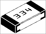
I work the the best people in the world. I was trying to figure out these numeric resistor codes, and my coworker Laura immediately pointed me here here.  Here's an example from that page:

First two digits: two digits in the value.
Third digit: number of zeros after the first to digits.

334 = [33][0000] = 330k ohms
440 = [44][] = 44 ohms (not 440, the zero means zero zeros!)
000 = link (no resistance)

Wednesday, February 9, 2011

an Arduino product idea

an Arduino product idea

One problem I have with building arduino projects is that I had to take them apart when I started the next one.  I solved this of course by getting some extra breadboards.

But, now I have the problem that I've got a couple of projects, but they're a bit of a hassle to rewire to the arduino board when I want to use them.  I've got the connections written down, but it takes some time and if I make a mistake then it's a pain to troubleshoot.

I know, basically I'm a spoiled software guy.

So, here's two ideas that would make this a bit easier:

Idea 1: Header Extensions

Development cards like the Uno have four sets of  has four sets of header pins (is this what they're called?  the ones you stick your wires into) -- two with 8 pins, two with 6 pins.

It would be nice to have a set of labeled extension headers.  The wires from the breadboard would be inserted into the header, and the header would be inserted into the header on the board.  Some kind of marking or coloration for orientation purposes would be nice.

That way, connecting a project would consist of just connecting the headers, and it would be easy to swap between projects by just swapping out the headers.  It would be clever if the header was easy to write on (e.g., not black)... then you could write the project or file name that needed to be loaded for that breadboard.

It seems you could make your own out of the breakaway female headers, but it would be nice to be able to buy a bag of these.  If they were custom-made, they could even take the header gap into account, and you would only have two header extensions per project.


Idea 2: Header Jumpers

This might be problematic in that it would make your breadboard too big.  Instead of a a header for holding your project wires, all project wires stay on the breadboard.  You then make 6 and 8 wire "extension cords" with a header on each end.  You specify the top 16 rows on the breadboard are for the header jumpers, and connections on your breadboard go to the BCDE holes on the breadboard.  The A holes (lol) would be for the jumpers.

Again, you could make these with the female headers, and custom pieces could reduce the number of jumpers down to two.

So what do you think?  Am I once again looking at a totally solved problem and making everyone roll their eyes in embarrassment?  Let me know if you've got a nice solution for this!  And if this idea happens to make you rich, send me a set, OK?

Friday, December 17, 2010

[Bare PCB] Arduino ProtoShield [Bare PCB] Arduino ProtoShield [BPC004] - $2.50 : iStore, Make Innovation Easier

[Bare PCB] Arduino ProtoShield: "The ProtoShield mates with the Arduino USB board and gives the user a small soldering area, two general LEDs, access to a BlueSMiRF socket, a general pushbutton switch, and most important of all - the Arduino reset switch is brought to the top level."

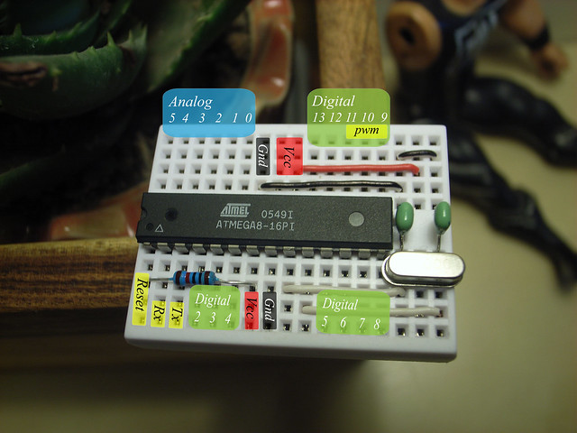
Standalone Arduino mini pin mapping | Flickr - Photo Sharing!

Standalone Arduino mini pin mapping:

Nice and cheap Arduino.

Bare Bones Board Kit | Modern Device

Bare Bones Board Kit | Modern Device: "The Bare Bones Board (BBB) is an Arduino-compatible board (Freeduino) that implements the functionality of the Arduino Duemilanove/Diecimila, on a smaller printed circuit board, by removing the USB communications chip to another board."

The Basics - Very Basic Circuits

The Basics - Very Basic Circuits:

Pull-up and current-limiting resistors.

Wednesday, December 8, 2010

Teensy USB Development Board

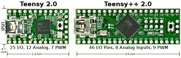
Teensy:
"a complete USB-based microcontoller development system, in a very small footprint, capable of implementing many types of projects." 

It has it's own software environment, but can also run Arduino sketches using TeensyDuino:
Many type of sketches are able to run on the Teensy! The digitial I/O pins work with digitialWrite(pin,value), digitalRead(pin), and pinMode(pin,mode). The PWM pins can be used with analogWrite(pin,value). Eight (8) pins can be used as interrupts with attachInterrupt(). The Teensy++ has 8 analog inputs that can be used with analogRead().