Showing posts with label _toc:Turnigy 9x. Show all posts

Sunday, January 19, 2014

Taranis Module Pin-Out


Courtesy of RCG user smoothvirus, here's two shots showing the pinout for JR-style modules.  The first is an actual JR radio, the second is the motherboard on the Taranis.

This should be the same for 9x and 9xr as well.

It was suggested that it would be useful to measure the voltage under load from the module connectors when calibrating the voltage.


Monday, November 19, 2012

Source: FS-TH9X-B-Module +Antenna

I've been looking for this for a while... just the FlySky module for the 9x.  $21.50 at the time of posting. At rcmodelpart.com.

Friday, November 2, 2012

Some quick er9x Notes

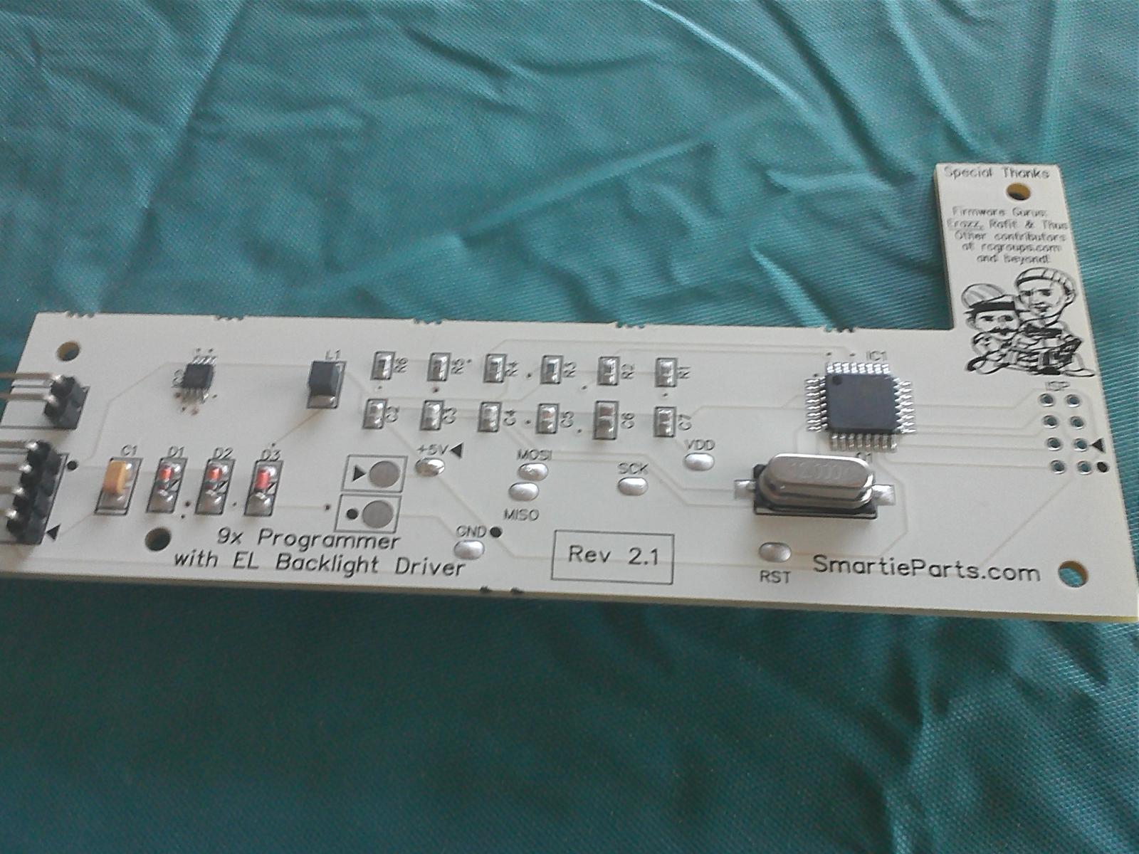
Here's a snapshot of my SmartieParts board installed.  For maximum fun, post on RCGroups and call it a SmartiePants!

Full er9x manual here.

Menu Quick Start
  • [LEFT LONG] : radio setup (six screens); stick calibration on screen 6
  • [UP], [DOWN], [LEFT], [RIGHT] : various display modes
  • [MENU LONG] : model select
  • [EXIT LONG] : reset timer
Some Mixes

Throttle Hold.
THR stick is passed 100% to channel 3; range -100 to 100
if throttle hold switch is off (up), the value -100 replaces the stick value.

    CH03   +100% THR 
         R -100% HALF Switch(!THR)

Ardupilot Mega, 6 positions on AIL DR, F.Mod.

    CH05   -96% HALF Switch(AIL)
           +90% HALF Switch(ID0)
           +45% HALF Switch(ID1)
           +17% HALF Switch(ID2)

ELE DR to channel 6.
I'll use this for the "find me" beeper.
If the switch is off, channel value is -100; if on, +100.

    CH06   +100%FULL Switch(ELE)

Tuesday, October 30, 2012

DSM2/DSMX JR Module, Turnigy 9x Compatible

I've been looking for one of these for quite a while.  Spektrum had a JR-compatible DSM2 module, but it was almost $100.  But now HobbyKing has them for $30.

OrangeRX DSMX/DSM2 2.4Ghz Transmitter Module (JR/Turnigy compatible)


This is great news for anybody that has a Turnigy 9x transmitter and

  • loves Parkzone small flyers such as the Night Vapor and Champ (like me!)
  • like the orange receivers for their park flyers
  • Looking for a Tx/Rx pair with failsafe
DSMX binding example here.


Mine's on order, I'll update this space once it comes in.


Update

The first batch sent by HobbyKing had a firmware bug.

executive summary:
  • it only affected the first batch that was sent
  • it's been fixed
  • newly ordered units are not affected
  • if you use er9x, you can work around the problem but can only use 6 channels
symptom:
  • Ch. 2 is flaky
  • seems to be related to frame timing
workaround 1, if you have er9x:
  • tested against OrangeRX and Champ with built-in RX:
  • - on menu 1, set:
Proto PPM 8CH 200 mSec
PPM FrLen 20.0 mSec
  • - on mix menu, set
ch 1 100% THR
ch 2 -100% AIL (i.e. reversed)
ch 3 100% ELE
ch 4 100% RUD
workaround 2, only works with external Rx:
  • avoid Ch 2, route whatever would normally be plugged into Ch 2 into Ch 5
  • works if you have discrete Rx
  • of course, doesn't work with any built-in Rx since you can't change the channel options

Saturday, October 27, 2012

er9x Success!

Hooray, er9x installed and seems to work!  Attached is a screen dump of the   eePe settings.  I used the SmartieParts board, but didn't hook up the backlight... maybe later.


My contribution to the user docs:  Here's the parms I used. Also note: the SmartieParts board is USB powered, but the 9x CPU is not.  So turn on your Tx power!

provisional APM setup like this:

CH01   +100%AIL 
CH02   +100%ELE 
CH03   +100%THR 
CH04   +100%RUD 
CH05   -96% HALF Switch(THR)
       +90% HALF Switch(ID0)
       +45% HALF Switch(ID1)
       +17% HALF Switch(ID2)

Monday, August 27, 2012

SmartieParts -- one per Turnigy 9x?

I sent this query off to the SmartieParts people:

 Can I use one SmartieParts board to configure 2 
 Turnigy 9x units? in other words, can I use
 the SmartieParts board to install ER9x or similar
 and then remove the SmartieParts
 board?  (Of course, that 9x unit won't be
 able to take advantage of the enhanced
 LED features.)

And got back this response.  It's pretty good information that I haven't seen elsewhere, so I'm taking the liberty of posting it here.  I ended up not ordering a second 9x, so the issue became moot for me anyways!

(update: after installing my SmartieParts board and getting some experience with it, I find I agree with Steven's notes below.)

Steven writes:

Yes you *can*... but I don't think you *should*.  And its not just because I want to sell more kits :) Honestly... there are good reasons:


  1.  Most people quickly realize that they need to update *frequently* because the firmware is in constant development.  There are regular updates (it is slower than it used to be... but still).  Swapping is a pain.
  2. The plastic that you're screwing into... it just isn't designed for constant assembly/disassembly.  You'll strip out the plastic eventually.  That goes for both the main case screw holes as well as the risers that my board screws onto.
  3. Even if you don't frequently update your firmware... one of the huge benefits of a permanently installed programmer using er9x/eepe combination is that you can easily and quickly define and tweek your models' settings on your computer and transfer them to your radio rather than using the less-intuitive radio menu controls.
  4. Similarly, you can hold literally millions of models on your computer but only a handful on your radio.  But with the programmer, all you need is to hook it up via USB and you can transfer whatever models you want at that particular time.

So really... its best to have a permanent connection in each radio.  That's the biggest "complaint" (if you can call it that) people have about my kit is that it is too expensive to outfit it in multiple radios.

At the risk of talking myself out of a sale... I usually advise people with multiple radios to instead buy one cheap-o USBasp programmer and practice up on their soldering skills and solder a permanent connector into each radio and use the one USBasp externally.  See... comparing my $35 programmer to a $10 programmer for one radio is only a $25 difference and that's easily justified by not having to solder and risk damaging the radio... but when you do the math for 2, 3 or 4 radios (or whatever)... now the difference is much larger.  With that said, there are MANY people who have bought multiple kits from me!  There's one guy that has 8 radios and 8 of my kits and he swears by it!

I hope that helps with your decision making.

Steven Morehouse
SmartieParts.com


Tuesday, April 17, 2012

Six-position APM switch for Turnigy 9x

This looks like a pretty nifty thing to do, courtesy of the ever-awesome HappyKillmore.  Basically it swaps out the pitch trim pot with a six-position switch that maps to the six APM control modes.  It's based on an original idea by Max Levine.  Video here.  Ready-made unit here, and here for kit that needs some soldering.

Sunday, March 18, 2012

FrSky installed, 9x module rejiggered

 Here's my FrSky module.  HK was out of the new model with telemetry, so I got the older model from Range Video.  Once the original 9x module was removed (more on that below), it was a simple matter to plug in the transmitter module and bind to the two receivers.
 I got the patch panel as well.
 Here's how the patch panel looks when installed.  I'll experiment with the range, it may be necessary to hold the transmitter a bit higher than usual?
 Here's what the transmitter module looks like from the side.  Very nicely, the  antenna mount points forward and there's a flat surface for the receiver to rest on.
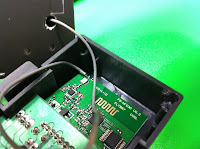
 Here's my rejiggered 9x module.  I should have taken some pics of the disassembly, but it's pretty straightforward.  Open the Rx case and loosen the screw that holds the antenna.  Open the module and remove the board.  Unsolder the antenna from the board, and remove the antenna and wire.  Don't bend or break the wire, it's actually a coax cable soldered onto two pads on the board.  Once the 9x module has been removed, you're good to use the FrSky module.
 I drilled a hole for the coax and ran the antenna through.  I epoxied the antenna over the hole, scoring the module cover and drilling some extra holes around the base for the epoxy to hold onto.

Here's an alternate method for removing the antenna that doesn't involve unsoldering and resoldering the connection.

 Resoldering the antenna cable needs a bit of care.  The two parts of the coax cable need to be soldered onto the two pads of the circuit board.  Study the board carefully before unsoldering and you'll see what needs to be done.

It turned out to be a lot easier than I thought it would be.  I didn't have to add any more solder or flux.  Hot glue the board into place as it was.
Here's what it looks like from the bottom.  Not quite as well as nice as the flat bottom of the FrSky module, but it doesn't seem to be too bad.  I'll point the antenna straight down when flying.

Wednesday, January 11, 2012

FrSky Notes

Thinking to upgrade to FrSky... here's some random notes.

Bruce has a nice tutorial on installing the DIY Kit.  And here's another.

Andreas has these on order:
It looks like going this route is simpler, just need to remove the old module and antenna, and snap the new module in.  The 9x is compatible with the JR module, not the Futaba.

There's a bunch of confusing bits about telemetry.  (Update: which can safely be ignored asFrSky has discontinued all non-telemetry Tx)

Transmitters
  • V* series are one-way (no telemetry) -- discontinued, FrSky only making telemetry-enabled transmitter modules now.
  • D* series are two-way (telemetry).
Receivers
  • D4FR: voltage only
  • D6FR: two external AD inputs. you can use one with a voltage divider for pack voltage
  • D8R: two external AD inputs, and serial port
Thanks ExplodingLemur for this great information!

Repackaging the original 9x radio.

Azure Engineering has a nice way of doing this.  The end result is that the 9x is now a pluggable module like the (non-DIY) FrSky module.


Other bits:
  • Looking also for some definitive information pages on all the above.  Somebody tell FrSky they should get a web page!


Sunday, October 30, 2011

LiFe battery in Turnigy 9x

 Here's how the 1500 mAh LiFe fits into the Turnigy 9x transmitter.
 It uses the servo-style connector.  From the left, it goes black-red-empty.  I put a sticker in so I won't forget it.
There's plenty of room inside the battery compartment.  I put the wires on the right side.  The cover fits on very easily now!

Sunday, July 17, 2011

Trainer Switch mod for Turnigy 9x

Strangely, the 9x trainer switch operates differently than most radios.  By default, control is given to the student, and the instructor must pull the switch up to take control.

You can reverse the switch, but then you'll have one switch backwards for the infamous "switch error" startup mode.  (actually, I'm used to that mode now and rather like it!).

Here's a simple hardware mod using a spring and two pieces of plastic tubing to hold the switch in instructor mode.  It's from a video review by Thomas Lombardi. Trainer switch discussion starts @3:34, the solution starts @4:42.

Update: I installed er9x which allows the trainer switch to be set properly.

Saturday, May 7, 2011

Turnigy 9x mixing for ArduPilot Mega

Tom Paton deserves a PhD in obscure radio settings for figuring out how to mix Turnigy 9x mode switches:
        http://rcav.posterous.com/programming-an-ardupilot-mode-switch-for-turn
He has a great writeup explaining the details of what he did... here's my quick-ref version.

ArduPilot Mega Functionality

       THR-CUT    F-MODE    POS        FUNCTION
           FWD    N           0        manual
                  1           1        stabilized
                  2           2        fly-by-wire-a
          BACK    N           3        auto
                  1           4        loiter
                  2           5        rtl

Basic Idea

  • Set the Throttle Hold Button to control Channel 5.
  • Add a mix, such that putting the F-MODE into NORM position subtracts 20.
  • Likewise, for F-MODE in position 1, subtracts 50.
  • Likewise, for F-MODE in position 2, subtracts 100.
  • This gives us 6 discrete values that will be broadcast on channel 5.
  • These 6 values map to the APM control function values.

    Setting The Mix
    • Set Channel 5 to Throttle Hold
              [FUNC SETTING] [AUX-CH]
                    CH5    THRO-HOLD
    • Set mixes 1-3
              [FUNC SETTING] [PROG MIX]

                      MIX1    MIX2    MIX3
              STATE     ACT    ACT    ACT
              MASTER    GYR    GYR    GYR
              SLAVE     FLP    FLP    FLP
              OFFSET    000    000    000
              UPRATE   -020   -050   -100
              DNRATE   -020   -050   -100
              SW        ID2    ID1    NOR
       
    • Check the Settings with the Display Menu.  There should be 6 discrete values.
              [FUNC SETTING] [DISPLAY]
     Further Mixing Information

    The manual has a unique perspective on mixing.


      Saturday, March 12, 2011

      Turnigy 9x notes

      Here are some notes on:
      Backlight kit.

      I got one, it's really nice!  You have to install it yourself, but it's not very hard.  Be careful if you're taking out the screws for the first time.  Note that the PC board has two sizes of screws.
      Receiver Polarity
      • Signal on top
      • Ground on bottom
      Receiver Channel Assignments
      • channel 1               ailerons
      • channel 2               elevator
      • channel 3               throttle
      • channel 4               rudder
      Unassigned
      • channel 5  (I assigned to GEAR)
      • channel 6  (I assigned to THRO HOLD)
      • channel 7
      • channel 8

      Radio Knobs and Dials
      • thro hold (cut)         left front bottom
      • gear                          right front top
      • pit trim                    left top dial
      • hov throttle            right front dial
      • hov pitch               left front dial
      Entering Name
      • To select the letter, do a "long menu", hold down the menu key for a half second or so.
      • Some programmer has a lot to answer for! 
      Throttle Reversed?

      If your throttle is reversed, you may have made a mistake when setting the sticks to mode 2.  If you set the mode, DO NOT push menu when it asks to reverse throttle, just push exit.

      Weird MODE?

      On the screen, you may see you are in MODE 1 when first starting up.  You're not in "mode 1" as in sticks, you're on "model 1".  MODE=MODEL.  This was what led me to me mess with the mode and end up reversing the throttle as mentioned above.  Don't be fooled like I was!
        Binding Instructions
        • turn off transmitter
        • plug ESC into channel 2
        • bind plug into BIND
        • add power to ESC
        • Step back at least 6 feet (this seems IMPORTANT!)
        • push bind button on back of transmitter
        • power on transmitter
        • wait for receiver light to stop blinking
        • power off receiver
        • power off transmitter
        • remove bind plug
        • power on transmitter
        • power on receiver
        • test!
        Replacement Battery

        Some people have recommended this as a superior alternative to putting NiCad batteries in the stock battery holder.
          Whatever you do, DON'T REVERSE BATTERY POLARITY, many people have reported smoking their receiver by doing this.  There's some suggested fixes involving soldering some diodes into the battery circuit on the motherboard.

          MIXING

          Possible ArduPilot mix formula here:
          http://rcav.posterous.com/programming-an-ardupilot-mode-switch-for-turn

          FAILSAFE

          Short story: failsafe only works in PPM mode. :-(

          TODO
          take some pics