Showing posts with label construction. Show all posts

Friday, June 14, 2013

OHD Update, and Portrait of the Drone Maker as a Young Man

 Here's an update on the One Hour Drone (OHD).  It was bare again after Andreas used it as a parts donor.  Second generation drone enthusiast Alexander and I wanted to refurbish it and kit it out with new electronics. We had discussed tossing the Wago-attached power distribution unit, and that's what we did, replacing it with a Hobby King PDU.
 We had to pry off the top plate of the quad (the down side of super-gluing everything together!) but managed to do so without mangling things too badly.  This height looks about right for the PDU to be safely ensconced in the frame.
 It turned out we didn't have any spare 4-40 1'' bolts.  We got some 6-32's in a bulk pack coz they were a ton cheaper.  They turned out to be too big for the motor mounts, so we had to drill out the motor mount holes with a 1/8'' bit.


Wednesday, October 26, 2011

APM carrier for Hawk Sky and related planes

Inspired by the new Bixler Accessory Chassis on diydrones, I thought I would tidy my own setup and make my own adaptation for the Hawk Sky.  I haven't quite finished it but it looks promising enough to write up, and I think something similar would work on other models with a front hatch.

I cut the horizontal top plate using the opening as a template.  I just cut the cardboard "close enough" and then traced the opening directly onto the cardboard.  I used scissors for the cutting.

 I then did the same for the forward and rear risers.  I attached the three pieces with epoxy.  I positioned the pieces on the plane and then spread the adhesive on the front and back joints.  I used enough so that the joint didn't need any extra reinforcing.  Note that the fuselage opening bends down towards the front.  I attached the top plate to the front riser in such a way as to keep the top plate level.
 I tried a couple of different ways to attach the APM.  What eventually worked best was a cardboard carrier  bent to the appropriate size and hot glued to the top plate.

I cut some holes to run wires, see the ABC lights, and reach the reset button.  I attached the xbee and GPS on the top plate with velcro.  I didn't make a GPS mount like diydrones did; if I have reception problem I will do so.
 I uncased the Turnigy 9x receiver both to save weight and get clearance for the battery.  I replaced the standard 3-wire connectors with single wire connectors.  Later I'll get the rectangular 6-way connector and use that instead of multiple single wire connectors, but it doesn't seem to be a problem for now.
 The unit sits on top of the battery.  With the receiver case removed, there's just enough clearance for the 3S 2200 mAh 15C battery.  I velcroed the reciever on the bottom and hang the antenna wire out the side.  That's roughly equivalent to what I've been doing and haven't had a problem so far.  I provided some strain relief for the antenna by hot gluing it onto the board.
c
AUW for the unit with velcro is 13.3g. Still to do:  put some magnets to hold everything down, velcro or otherwise attach the APM to the lower carrier, and attach the pitot tubes.  I'm hoping to attach the tubes to the carrier if I can.

I'll update later when I've applied the finishing touches and gotten the thing into the air.

Sunday, May 22, 2011

Wing Dihedral Calculation

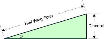
Given an angle, the wing dihedral is the amount the wingtip rises above the wing at the center of the plane.
Sine Ø = Dihedral ÷ Half Wing Span

So, a 4 degree dihedreal for a Blu Baby 33 would be sin(4 degrees) * 33/2 = 1.168.

Prop each wingtip up with a 1.2 inch block and attach along the centerline.

Source

Blu Baby Control Rods

Somebody on RC Groups asked about attaching the control rods on the Blu Baby.  Here's how I did it, with the control rods on the outside.  It  doesn't look as nice as running the rods internally, but it's a lot easier.  I wanted the control rod to be as light as possible, so I used 1mm carbon fiber rod, running through plastic coffee stirrers.

 Here's the servo cutout.  Trim the foam where the servo tabs are so that the servo will sit flush.  Run the servo wire in and attach with a very small amount of hot glue under each tab.

The servo attachment is a straightened paper clip with a Z-bend.  I put both the CF rod and the paper clip into 1.5mm shrink wrap, and added a couple of drops of CA.  Heating the shrink wrap gave a very tight, even connection between the two surfaces for the glue to bond to.  Any excess CA will drip out when heating, so be careful.


Hot glue a control horn to the rudder.  It's attached with a Hobby King 1.5mm screw mount. If you save this step for last, you can find the "natural" spot where the control rod will go.

 You can see here that the control rod runs through two plastic coffee stirrers that have been taped together and trimmed to length.  I attached them to the plane with three spots of hot glue, the tiniest I could use that still held the coffee stirrers firmly in place.

Green note:  These are recycled coffee stirrers that were used to stir organic half and half into free-trade organic coffee!
 Here's the inside of the plane, showing that the servos are flush mounted against the monobody.  It also shows how tight the inside is on a Blu Baby 33 with one inch monobody, which is why this technique is so much easier than running the control rods on the inside.  Later I'll try a Blu Baby with 2 inch monoblock, where I can actually fit my fingers inside.
Attach the elevator opposite the rudder.

Saturday, April 23, 2011

EasyStar Rudder Mod

 Here's my rudder mod for the Easy Star.  Executive summary:  Dubro hinges, twin credit store cards (store card, thinner and lighter).

 I connected the rudder to the vertical stabilizer using a pair of Dubro hinges.  This made the throw much smoother.  Andreas told me about this... cut slots in the stabilizer and rudder, and insert the hinges into the slots.  It will be nicely aligned.  I used the smallest amount of CA I could, and squeezed the CA deep into the slot before inserting the hinges.  Don't get glue on the hinges, or they won't hinge!
 Instead of the traditional credit card, I used a CVS store card, being thinner, lighter, and a cheerful red color.  One problem: I didn't like the asymmetric angle when one card was attached.  It doesn't cause problems when flying, since you just straighten the "extended" card rudder when attaching to the servos, but it looks a bit untidy.

I had an extra card, so I tried squeezing them together... as you can see in the second picture, it looked quite nice.  It added an extra 3.2 grams of weight to the tail,, but I don't think that will be detrimental.

 I taped the long edges together, then CA'ed that edge with some kicker.  I then CA'ed the two cards squarely onto the rudder, keeping the same appearance in the second picture.  I put a drop of glue into the gap and held it shut to keep the nice curve.

Following that, I attached the built-up rudder to the vertical stabilizer using the hinge and the method detailed above.  It was a bit trickier since I had to get both hinges aligned at the same time.  It doesn't hurt to dry-fit the hinges and reinsert them several times in order to get a nice smooth glide for when you're inserting the hinge with glue.

I set the servo attachment to the second hole, which looks like about the right amount of throw.  Instead of discarding the tape, I tidied it up around the edges and left it in place, mainly for the nice clean line it had.

Overall, I was pleased with how it looks and operates.  And I can tell people the rudder mod was done with Extra Care!

update: very honored for this to be included in the RCGroups E* Mods post!

Thursday, January 20, 2011

Push Rods Revisted

Filling in a bit more of what I have learned about micro pushrods.

  • For small flyers, the reference standard seems to be the Du-Bro Micro Pushrod System #852 (30" x .032"):
New Du-Bro Micro Pushrod System. (2) 30"x.032 pushrods, (2) 30" pushrod housings and (2) micro E/Z Links and (2 Mini E/Z Connectors. Great for indoor and park flyers! 2/pkg.
  • The EZ links are: Mini E/Z Connector (Cat. No. 845)
  • Hobbyking links come in 1.5mm and 2mm.
  • The EzFly kit comes with 1.5mm carbon rod, 4 wire z-bends, and heatshrink.
  • Heatshrink z-bends to the carbon rod, and heat.  Put a drop of CA and allow it to wick into the heatshrink
  • Don't try putting the z-bend in the center of a hollow rod, it won't stick.
  • You can use a z-bend on both sides of the push rod.  Center the servo, align everything, and heatshrink the z-bend in place.  Once you're convinced everything is properly aligned, Apply CA.
  • Somebody uses TIG welding wire for the rod.
  • A lot of people use 1/32'' (almost 0.32) piano wire.  These need to be fed through a housing to maintain stiffness.  Attach the housing to the plane somewhere.
  • The z-bends can be made from a paper clip or .072 piano wire.
  • For a housing, try plastic coffee stirrers. Heatshrink together if you need them longer.
Push Rod Weights
  • 1.5mm CF
  • 2mm CF
  • 3mm hollow CF
  • 1/32'' piano wire
  • z-bends
  • heatshrink
  • coffee stirrers

Tuesday, October 5, 2010

Balancing servo throws

from: Setting up your Airplane
 Preferred servo orientation to maximize stiffness:

Linkage setup:
  • dimensions "A" and "B" are determined by what the plans call for with respect to the total movement of the control surface (up/down, left/right, etc.) and how much travel your servo has.

    set radio for normal, high-rate throws.
  • at control surface, mount the control horn so that distance "A" is as large as possible -- about 1" or so for large aircraft, 3/4" or so for smaller airplanes; commensurately larger for giant scale or smaller for park flyers.
  • deflect the control surface to the maximum the plans call for, and measure the (horizontal) distance that the hole in the control horn moves. Call this dimension "C".
  • Using radio, center servo arm.  run the servo to its extremes and measure the distance some particular hole in the servo arm moves. Choose the hole that is closest to dimension "C" that you measured at the control surface. The distance from the middle of the servo attaching screw to that hole is dimension "B".
  • fix control surface in neutral position, and measure the distance between the hole on the servo arm and the hole in the control horn with the servo in its neutral position.
  • manufacture a straight rod and attach it to those points.
  • mount the servo, making sure that the servo arm is perpendicular to the control rod, as shown, and that the control horn is also perpendicular to the rod.
  • turn on your radio again and run that channel to its extremes and measure the throws at the edge of the control surface. Now reference the plans for your model. Are the throws too much, too little, or just right? If too much, increase dimension "A" (or decrease "B").  If too little, reduce "A".
  • the throws in each direction should be identical. If not, check that the setup is as shown above, with 90 degree angles at both ends. You may have to adjust the neutral on your servo, or bend the arm at the control horn, but try hard to equalize those throws!
  • What you’re doing here is maximizing the utilization of your servo’s power. By using the entire rotation of your servo arm to cause the control surface to move its maximum distance, you’ve used the mechanical advantage of the servo to its fullest extent - all the power your servo has is being used.
  • If you merely install your servo and rod without regard to the total desired control throws, and the distance "B" at the servo is longer than at the control arm, you will have to reduce the maximum servo arm rotation allowed in order to keep the control surface movement at the correct distance. Result: poor utilization of your servo's power—you’re only using part of it, and resolution suffers as well.
  • If distance "B" at the servo is shorter than at the control arm, the opposite ensues, and you’ll most likely overdrive the servo, perhaps causing binding or other equally devastating problems, or you won’t get the full throws desired at the control surface.
     

Monday, August 9, 2010

Stick movement and Control Surfaces

Because I seem to live in backwards-universe, here's what the sticks do.  Thanks to the NASA Aeronauticshttp://virtualskies.arc.nasa.gov/aeronautics/5.html guide for the images.

elevator
  • stick back, elevator up
  • stick forward, elevator down
rudder
  • stick left, rudder to left
  • stick right, rudder to port
aileron
  • stick left: left aileron up, right aileron down
  • stick right; left aileron down, right aileron up