Here's how we attached LED lights to
Arcticopter 1.
LED strip lights are pretty amazing things. They're thin, have LEDs mounted on flexible strips with which carry the current, and have sticky backing. We bought four colors: red and green for left and right (as per standard aviation habit), white for front, and blue for the rear. They come in 1 meter strips, and can be cut every 5 cm (every third LED) to make the length you need.

Here's the shopping list:
- - LED strips (non-waterproof): Red, Green, White, Blue
- - Brushed ESC
- - Connectors
- - Wago Connectors -- these are great for temporary wiring, since it can hold five wires together and the snaps allow wires to be added and removed individually.

There are two different kinds of light strips -- waterproof and non-waterproof. For aeronautical purposes, get the non-waterproof, they are a lot lighter... 12 grams vs 36 grams per meter. Unless of course, you're making an amphibious flying vehicle!

The current draw for four 1-meter strips is 0.1, 0.4, and 1.1 amps at 11.4 volts at min, half, and full power (unscientifically measured by my turning the knob on my servo tester -- more on hooking things up below). I haven't measured with smaller strips, but I think the current draw will be smaller in proportion to the number of LEDs being driven.

Here are the two kinds of strips. Note that every 5cm there's a "cut here" spot. The waterproof strip has a nice scissors marking to leave no doubt.

On the far left of this photo, we can see there's a built-in resistor; we don't have to worry that we'll burn out the LEDs. In the middle we see the cut line. On either side of the line, we see the solder pads.


Here are side views of each of the normal and waterproof strips. You can see there's lots of plastic encasing the waterproof strip. Both have 3M sticky backing.
Wiring the Strips -- First Try
Here's my first try at wiring the strips. I used some
JST-RCY connectors (with leads:
male and
female) that I had laying around. It works, but I think it can be better -- lighter, smaller connectors, and with less wire clutter. See below for a second try.
The arms are about a foot long -- a 15-light, 25cm strip will fit perfectly.

I cut 2 each 25cm strips of the four colors: red, green, white, and blue. Some of the strips had the original wires attached; Since we want all the strips to be consistent in the wire length, we'll desolder those.
Soldering the Strips
[placeholder for LHS pic] I'll add some pictures later of the soldering. For now, I'll just note that I had some JST-RCY connectors attached to leads, and soldered those to the strips. The small circles next to the cut lines are solder pads.
Strip your wires to about 2mm, tin them, tin the solder pads with a blob of solder, and then "mash" the tinned wire into the solder blob. It will melt almost immediately and make a nice looking connection with your wire in the middle. When you tin the solder pads, there will be a thin covering film that will evaporate off and expose the pad. If you don't get a nice circular blob, try again.
If you're working with the waterproof strips, use an Exacto blade and push it straight down through the plastic. You can then lift the plastic off of the strip. Get as much of the plastic off as you can... you can melt through it with the soldering iron, but it's probably made of stuff you don't want to be inhaling a lot of.
Note that LEDs have polarity, and the strips do as well. Before you desolder the supplied wires, note which sides are attached to the hot and neutral wires. After you solder each pair of wires, stick them onto a convenient 2S or 3S battery -- if the strip doesn't light up, you've got the wires backwards -- desolder them and try again.

Here's the power harness I wired up... Eight female (note discrepancy of terminology) JST-RCY leads for each of the strips, and a male JST lead to plug into the wired ESC output (or to a battery, if you're skipping the ESC). It's heavy, and bulky when stuck into the frame, but it works. I soldered a female JST-RCY onto the ESC output leads.

Here's everything connected together and attached to a 3S battery. You can use a 2S battery if you want it dimmer, but it seems most people like the brightness from the 3S. I've got the ESC attached to a
servo tester. If you don't have one you can connect to a receiver and control with your transmitter, but you really should consider getting one -- it's cheap and saves you a lot of time at the workbench.

I used 8mm shrinkwrap to wrap the end of the strip. It doesn't seal up tight on the wire end, but it does do a good job of strain relief. If you know of a better way (funnel-shaped shrinkwrap?) please drop me a line!
Wiring the ESC
Wiring the ESC is pretty simple. Put your favorite battery connector on the battery end. If you don't have a favorite, the JST-RCY is small. That's what I will be using. On the other end, put whatever connector you've used to wire up your lighting harness. For my first try, that was a JST-RCY. For the second attempt, I'll try using a universal servo connector if the current isn't too much -- I don't think it will be.
Another option is powering the strips directly. It will work (because of the built-in resistors), but may give you much brighter lights than you want. This is especially important if it's dark, since they may clobber your night vision. Perhaps this could be controlled with resistors?
Wiring the Strips -- Second Try
coming...
Attaching the LED strips

Attaching the strips was pretty straightforward. I used blue tape to position everything temporarily to make sure everything fit.

I wrapped the inside wire for strain relief. You can see the big clump of wires below, and why I want to rewire this.

Here's everything attached and turned on. I'm hoping that it will be plenty bright for daytime use. It's sure bright sitting on my dining room table!


 Here's the shopping list:
 There are two different kinds of light strips -- waterproof and non-waterproof. For aeronautical purposes, get the non-waterproof, they are a lot lighter... 12 grams vs 36 grams per meter. Unless of course, you're making an amphibious flying vehicle!
 The current draw for four 1-meter strips is 0.1, 0.4, and 1.1 amps at 11.4 volts at min, half, and full power (unscientifically measured by my turning the knob on my servo tester -- more on hooking things up below). I haven't measured with smaller strips, but I think the current draw will be smaller in proportion to the number of LEDs being driven.
 Here are the two kinds of strips. Note that every 5cm there's a "cut here" spot. The waterproof strip has a nice scissors marking to leave no doubt.
 On the far left of this photo, we can see there's a built-in resistor; we don't have to worry that we'll burn out the LEDs. In the middle we see the cut line. On either side of the line, we see the solder pads.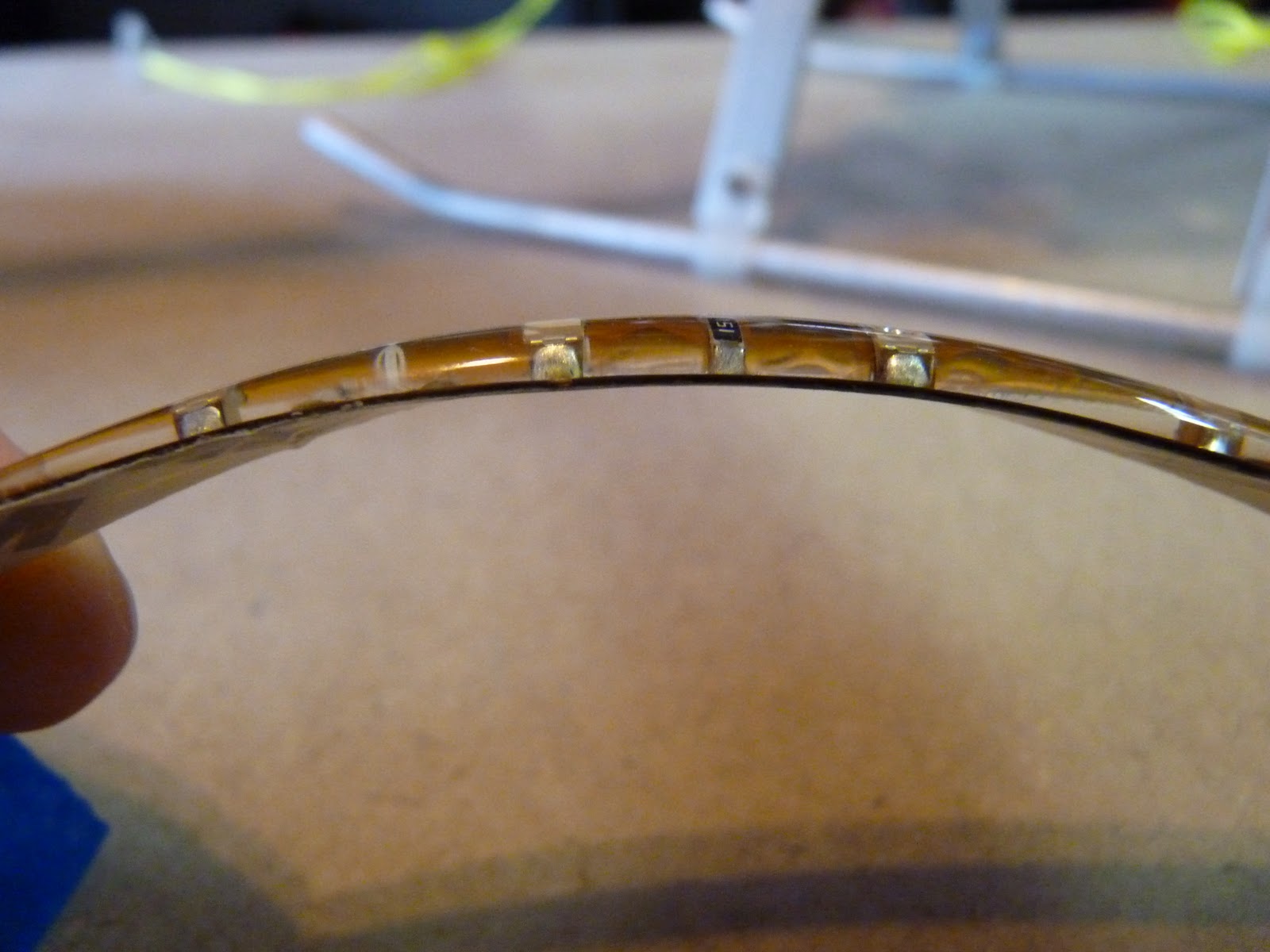
 Here are side views of each of the normal and waterproof strips. You can see there's lots of plastic encasing the waterproof strip. Both have 3M sticky backing.
 I cut 2 each 25cm strips of the four colors: red, green, white, and blue. Some of the strips had the original wires attached; Since we want all the strips to be consistent in the wire length, we'll desolder those.
 Here's the power harness I wired up... Eight female (note discrepancy of terminology) JST-RCY leads for each of the strips, and a male JST lead to plug into the wired ESC output (or to a battery, if you're skipping the ESC). It's heavy, and bulky when stuck into the frame, but it works. I soldered a female JST-RCY onto the ESC output leads.
 Here's everything connected together and attached to a 3S battery. You can use a 2S battery if you want it dimmer, but it seems most people like the brightness from the 3S. I've got the ESC attached to a servo tester. If you don't have one you can connect to a receiver and control with your transmitter, but you really should consider getting one -- it's cheap and saves you a lot of time at the workbench.
 I used 8mm shrinkwrap to wrap the end of the strip. It doesn't seal up tight on the wire end, but it does do a good job of strain relief. If you know of a better way (funnel-shaped shrinkwrap?) please drop me a line!
 Attaching the strips was pretty straightforward. I used blue tape to position everything temporarily to make sure everything fit.
 I wrapped the inside wire for strain relief. You can see the big clump of wires below, and why I want to rewire this.
 Here's everything attached and turned on. I'm hoping that it will be plenty bright for daytime use. It's sure bright sitting on my dining room table!

