Friday, September 2, 2016

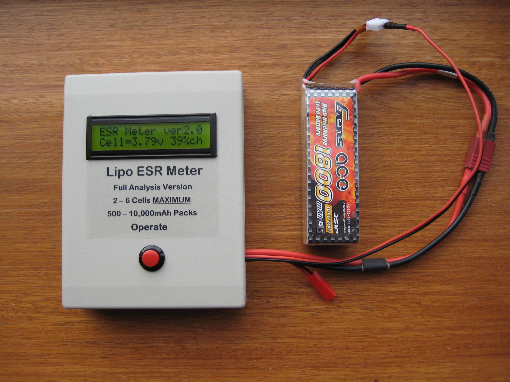
Links for Wayne Giles ESR Meter

Wayne is shutting down production himself as he moves on in retirement; I hope somebody picks it up!

Thanks Wayne, and hope you enjoy your retirement!


Here's some random links for posterity.

RCGroups Thread on V2 unit
RCGroups Thread on V1 unit
Unit at Progressive RC
Proof C Ratings are Useless  -- very true!


Four-Wire (Kelvin) Resistance Measurements

Due to the limitations of the two-wire method, the four-wire (Kelvin) connection method shown in Figure 2 is generallypreferred for low resistance measurements because it reduces the effect of test lead resistance. These measurements can be made using a DMM, SourceMeter SMU instrument, or a separate current source and voltmeter. With this configuration, the test current (I) is forced through the test resistance (R) via one set of test leads, while the voltage (VM) across the DUT is measured through a second set of leads (sense leads). Although some small current (typically less than 100pA) may flow through the sense leads, it is usually negligible and can generally be ignored for all practical purposes. The voltage drop across the sense leads is negligible, so the voltage measured by the meter (VM) is essentially the same as the voltage (VR) across the resistance (R). As a result, the resistance value can be determined much more accurately than with the two-wire method.

Note that the voltage-sensing leads should be connected as close to the resistor under test as possible to avoid including part of the resistance of the test leads in the measurement.

and another Explanation of 4 Wire Kelvin Testing.

This video covers the V1 unit:


blogodex = {"toc" : "ESR Meter", "idx" = ["Wayne Giles", "power", "batteries"]};
RC Receiver USB Adaptor

An interesting project from gregnau @ rcgroups:
http://www.rcgroups.com/forums/showthread.php?t=2714430

gregnau writes:

RC Receiver USB Adapter

Arduino based game controller adapter for regular RC receivers up to 6 channels.
It acts as an USB joystick, dispatching the channels values read from a PWM RC receiver. Aimed to be fast and responsible, though simple to use with automatic calibration function. It can be useful to play simulator wireless from the computer with your favourite transmitter. Compatible withWindowsMacLinuxAndroid,IOS.

Parts-list

Requirements
The .hex file and the supplied installer is only compatible with Sparkfun Pro Micro, do not try to flash it on other Arduino compatible devices. If you want to give it a go on other boards, then compile from source! Source:http://github.com/gregnau/wireless_rc_adapter
Installer should be easy as double-clicking the install.bat while the Pro Micro is plugged in. Everything is detailed to the screen, so if there is any error you can start investigating 

Worth checking before flashing!
hex-file checksum: d7065aed90c259e7ef3d8fe3dad3f1d7

Some jumperwires are needed to connect the receiver to the Pro Micro. Below on the picture you can see an example of wiring and setup in details.

Wiring
(it is attached below to the post, i have no idea how to put it here)
wiring.png

Manual
The Pro Micro boards usually have 2 leds side-by-side, which are the TX and RX status lights. These are used to reflect the state of the adapter:
On every startup these are flashing twice, then one of them is going off, the other one stays on. This means booted up successfully and ready to play.
But if they stay on, that means the adapter is in calibration mode. The calibration data is loaded and verified during setup,
but if these are incorrect/missing than it goes to calibration mode automatically.
Automatic calibration
Calibration process is the same as everywhere, the sticks, pots, switches on all channels must moved to their extents. Preferably more than once and in slow motion.
The leds are lit
During calibration there is no sending of joystick values to the host, there is no feedback at all, except it is in '#DEBUG_ENABLED' mode. Though in debug mode it's only using terminal to send data, there is no hid interface. While in normal operation after the calibration data is accepted and saved it goes directly to play mode. 
Manual calibration
Sometimes it is needed to re-calibrate the adapter, although there is valid calibration data saved. To achieve that just plug in the usb while pushing the attached button. Then everything should be the same as with automatic process.
---
> Still under development so any advice is welcome regarding the code or feedback on use! Only known restriction is the calibration autosave function accepts only if there is 6 working channels calibrated. In case you connect less channels then you always need to push the button to save calibration data.

blogodex = {"idx" : "radio"}

Reverse Engineering a Quadcopter

Michael Melchior has an interesting series of four articles where he reverse engineers a quadcopter, including the radio protocol.  It's really good, and he includes links to his code that listens to the radio.  As they say, read the whole thing!

(Part 1) (Part 2) (Part 3) (Part 4)


blogodex = {"idx" : "reverse engineering", "Michael Melchior"};

Colored Sealing Tape for Covering RC Planes

Here's a nice article on using sealing tape to cover foamies.  Read the whole thing!


http://rcfoamfighters.com/blog/?p=426
http://www.tapeplanet.com/Colored-Carton-Tape-s/149.htm

blogodex = {"toc" : "Foamy Tape"};