https://windcatcherrc.com/shop/
EastBay RC
Come fly with Mark in the lovely San Francisco East Bay!
Sunday, May 22, 2022
Friday, March 25, 2022
Wednesday, May 5, 2021
Monday, December 28, 2020
Eachine E130 Helicopter
Eachine e130 2.4g 4ch 6-axis gyro altitude hold flybarless rc helicopter rtf Sale - Banggood.com
- Flybarless, no collective pitch.
- The printed manual seems to disagree with some of the online specs.
- Protocol: DSMX DSM2 PPM "S-SUS".
- Battery: 2S 700mAh 20C, JST.
- Hover Switch? "It's for trimming up the helicopter. The controller will not remember trim settings between flights unless you use this button. To trim, first press the hover button for 5 seconds until the controller beeps, and its power light starts flashing. Then launch the helicopter, and be prepared to counter any uncommanded drift with the pitch roll stick. If you notice drifting, repeatedly press a corresponding trim button to negate that lift (those little buttons to the left and below the pitch roll stick). For example (Mode 2 controller), if the heli is drifting left, repeatedly press the right arrow trim button located directly below the right stick until the drift stops. If drifting forward, repeatedly press the back (down) arrow trim buttoned located left of the right stick until the movement stops. Once stable hover is achieved, land the helicopter, press the hover button again until it beeps and the light goes steady. Then turn off the helicopter and controller. The controller should now remember your hover trim settings for successive flights. By the way, there's also a gyro calibration for extreme drifting. Place the helicopter on a flat level surface, then move and hold both sticks to the lower left corner until the helicopters lights blink indicating that it is calibrating. Calibration is completed once the lights go steady. see less
- Rate Switch? "Top left button is the high/low rate button."
Monday, October 19, 2020
OpenTX Smart Throttle Cut
Logical switches:
L1 AND SFv L2L2 OR L1 L3
L3 a<x Thr -96
Special Functions:
SF1 !L1 Override CH3 -100 (then tick the "ON" box)
Mixing for Two-part Landing Gear
Mixers
CH6 SF Weight(+100%) Delay(u2:d2) Slow(u2:d2)
CH7 L02 Weight(+100%) Delay(u4:d0) Slow(u2:d2)
CH8 MAX Weight(+30%) Switch(SB-) Slow(u4:d4)
+= MAX Weight(+60%) Switch(SB↓) Slow(u5:d5)
Logical Switches
L1 CH6 > 95
L2 SF↑ XOR L04
L3 CH6 < -95
L4 L01 OR !L05
L5 L03 OR !L04
Mixing for Axial Rolls
Read somewhere:
Finally dialed in some aileron to elevator mix, so that there is some
down elevator when ailerons (right or left) are moving.
Your results may vary, after some trial flights I have now some 35%
aileron differential, and 25% aileron-elevator mix (positive for right
aileron movement, negative for left aileron movement), and the Wingnetic
now rolls the way it should.
Sunday, October 18, 2020
Friday, October 2, 2020
24V Power Supply Notes
Unit
HP Proliant Gen 8 Server 750W Power Supply Unit PSU HSTNS-PD29 656363-B21
RC Groups Threads
- How to convert Server Power Supplies - RC Groups
- Using two power supplies for higher voltage/capacity chargers: safety issues - RC Groups
- Converted DPS-750 PSU info_dump - RC Groups
- RC Groups - View Single Post - A simple high quality 12Volt 100Amp Power Supply- Part1
- My take on the HP server power supply. - RC Groups
- RC Groups - View Single Post - A simple high quality 12Volt 100Amp Power Supply- Part1
- Dell PE6800 Power Supply’s powers 2 FMA Powerlab 8’s.Completed - RC Groups
Thursday, September 24, 2020
Drop Ctrl Configuration Notes
Config Instructions:
- https://drop.com/talk/9382/how-to-configure-your-ctrl-keyboard
(DONT FORGET TO DOWNLOAD applet-flash-samd51j18a.bin) - https://drop.com/mechanical-keyboards/configurator/config/16042
Software:
- https://github.com/qmk/qmk_firmware
- https://github.com/Massdrop/mdloader/releases/tag/1.0.4
- https://github.com/Massdrop/mdloader
Some Notes
- https://www.storyspooler.com/using-qmk-for-lights-on-massdrop-ctrl/
- https://www.reviewgeek.com/19076/drop-alt-has-everything-you-want-in-a-custom-keyboard-except-the-soldering/
Create Config and download Bin
Running the Loader
$ ./mdloader_mac --first --download massdrop_ctrl_config.bin --restart
Massdrop Loader 1.04
Massdrop Loader Copyright (C) 2018 Massdrop Inc.
This program is Free Software and has ABSOLUTELY NO WARRANTY
Scanning for device for 60 seconds
......... ***** PRESS FN-B FOR 1 SECOND AND RELEASE TO REBOOT
Device port: /dev/cu.usbmodem141412201 (SAMD51J18A)
Opening port '/dev/cu.usbmodem141412201'... Success!
Found MCU: SAMD51J18A
Bootloader version: v2.20 Mar 27 2019 10:04:47 [ctrl]
Applet file: applet-flash-samd51j18a.bin
Applet Version: 1
Writing firmware... Complete!
Booting device... Success!
Closing port... Success!
QMK Quick Notes
# https://docs.qmk.fm/#/newbs_getting_started
# github fork qmk_firmware
brew install qmk/qmk/qmk
qmk setup marhar/qmk_firmware
cd $HOME/qmk_firmware
qmk compile -kb massdrop/ctrl -km default
qmk config user.keyboard=massdrop/ctrl
qmk config user.keymap=marhar
qmk new-keymap
qmk compile
qmk compile -kb massdrop/ctrl -km marhar
vi keyboards/massdrop/ctrl/keymaps/marhar/keymap.c
vi keyboards/massdrop/ctrl/keymaps/default/keymap.c
$ ls $HOME/qmk_firmware/*.bin
massdrop_ctrl_default.bin
massdrop_ctrl_marhar.bin
Tuesday, August 18, 2020
Jumper R8 Notes
RCGroups thread:
Midelic Firmware thread:
- Jumper R8 Receiver - 8-channel PPM/16 channel SBUS, D16 /LBT/D8 compatible firmware
- DIY FrSky X(D16) receiver - RC Groups
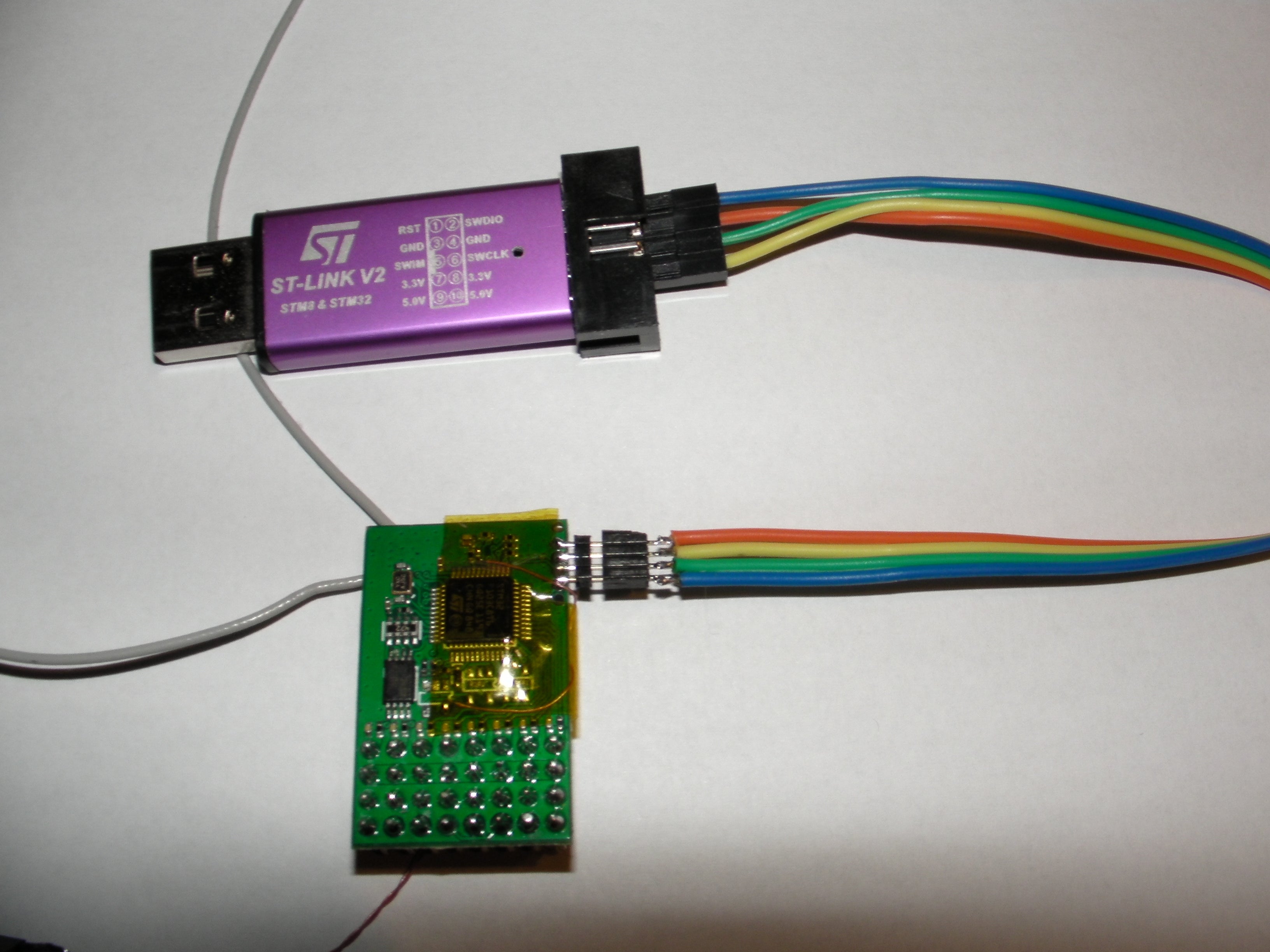
STM Flasher and Tutorial
- FLASHER-STM32 - STM32 Flash loader demonstrator (UM0462) - STMicroelectronics
- Flashing programs to STM32. Embedded Bootloader | Do It Easy With ScienceProg
- New All-in-one Software Tool from STMicroelectronics Makes STM32 Microcontroller Programming More User-Friendly
- STM32 F103C8T6 6Q25E 1193
- steady green: signal good
- blinking green: signal bad
- solid red: signal low
- blinking green: signal bad
- solid red: signal lost
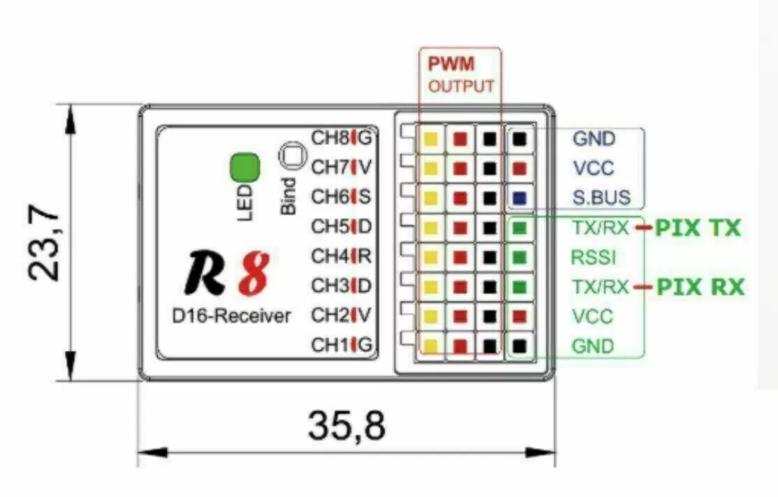
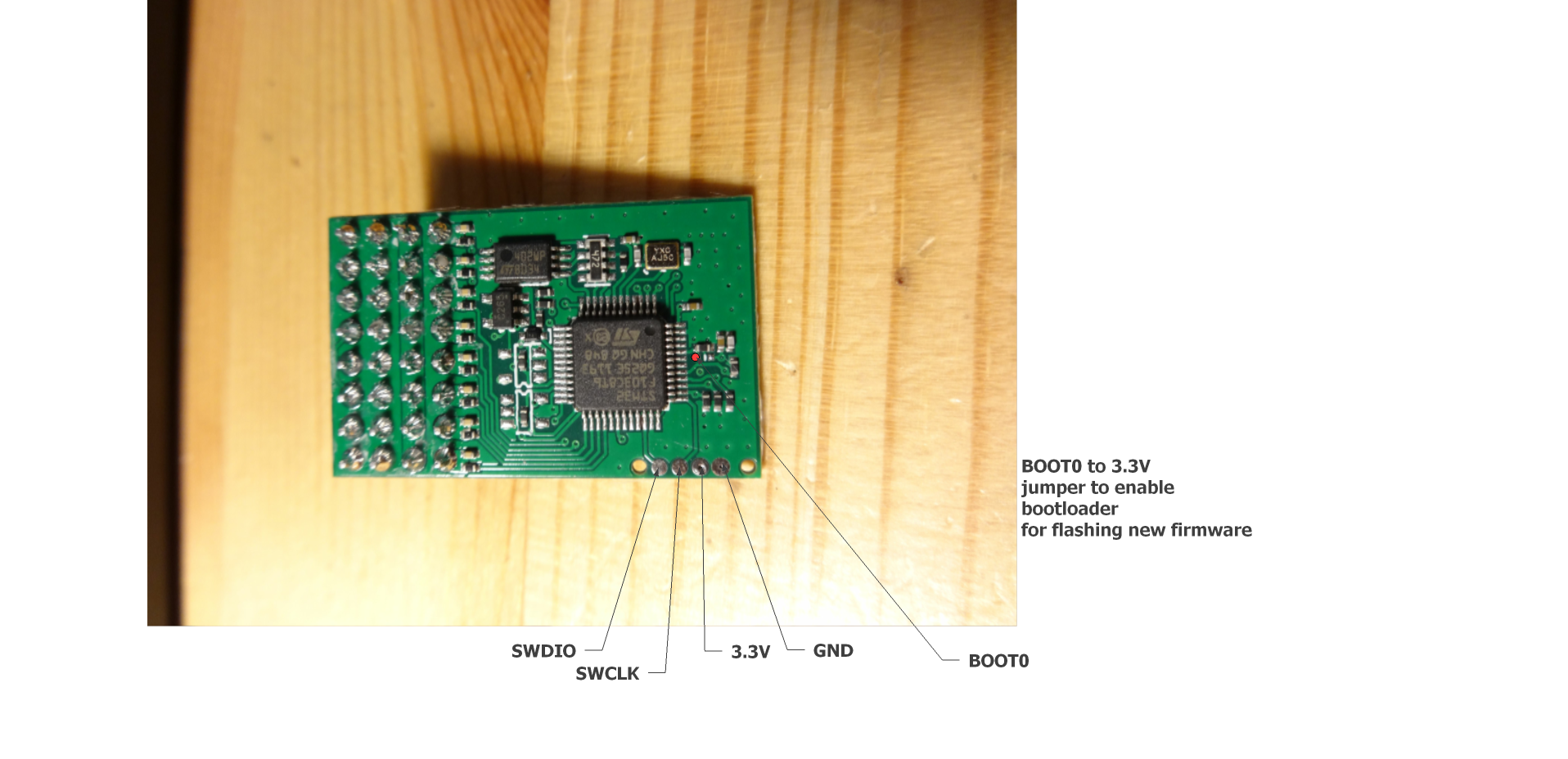
Flashing new firmware on Jumper R8 connections.
- Use STlink V2 programmer.
- connect STLink device ,press Target/connect.
- If you receive "Read out protection" enabled warning, go into "Option bytes" and disable it.
- Press "Erase/Chip" after that press "Program&verify" load the binary file to be flashed.


Monday, August 10, 2020
Powered Solder Sucker Notes
Some good tips from the Amazon page.
- BIT/DESOL3 is the replacement tip. Look at the other answers, they say it has a 2.1mm opening.
- This isn't made to be used like a pencil like the non-heating ones. The button is near the back! The way you hold it is (to explain in words here) by opening your (right) hand and placing it in your palm with the plunger push-down at the same side of your palm as your thumb. Wrap your hands around it. Your thumb is now right on the release button! Hold it like you are stabbing the pc board. Place perpendicular to the board, wait maybe 3 secs, then use thumb to press the button. No shifting, jerking, momentum issues, etc. Just lightly tinned holes/pads after you are done.
- For cleaning, Seller is wrong. Very cleanable. Instructions on pkg, but there is even a better way... Look closely at the housing/base where the plunger rod goes into the black end of the yellow tube. You can see the bigger outer housing you hold has a little partition at the top of the suction tube. The yellow tube is cradled in the outer tube. Use a small flat screwdriver and lever it slightly and it pops out - the whole tube. It comes apart for cleaning. An old toothbrush cleans the plunger well. It seems to all gather at the end of the plunger. It has a light coating of grease, probably silicone paste, so if you remove it by washing you may need to re-apply...
- Properly tin the tip the very first time you heat it up, and treat it like a soldering iron!--ie: keep the tip wet with fresh solder while you work. *Adding* solder to a joint you want to *desolder* is a "secret" well-known by the experts because it keeps the joint fresh and flowing rather than brittle and plasticized so that the solder flows well and the joint is cleaned nicely when you press the vacuum button. Also be sure to hold the iron vertical to get good suction when sucking. And let me repeat: if you say the iron is not hot enough you are WRONG! (in 98% of the cases). What you need to do instead is *add fresh flux-core solder* to the iron tip--get it all up inside the tip even, then place the tip over your through-hole leg to desolder and now the fresh solder will flow the heat right into the joint--press the vacuum sucker button and voila! You've just cleaned that joint perfectly!
- https://www.youtube.com/watch?v=UdGB7vD8ey0
Monday, August 3, 2020
HobbyKing Rarebear 620


Tuesday, July 14, 2020
Thursday, July 2, 2020
Ultrix CG: some random RCG
Do the bind inverted using the polystyrene brace from the box on a level surface
For flight switch the TX on, then the model.. then place the model down on some flat ground and wait for it to sort itself out..
Trimming is done in as3x mode, not safe... I adjust the push rod bends to raise both elevons by a tiny amount, I set mine with them raised by the thickness of the wing at the trailing edge..
With it set like that mine flies fine.. battery just stuffed anywhere in the nose.
I think its angle at bind affects its level flight so its worth rebinding, inverted, with the rear end raised a touch, so when its the correct way up the nose has effectively been raised and trying again..
Mine was going down at launch, not flat, this was initially sorted with TX trim.. and later rebinding.
As you can see from the video it was still going down slightly when the power/throttle was set lower, on the first launch.. but when the power was set higher it remained flat.. this was a nose heavy flight.. note the first launch was downwind, and this also makes a big difference....lol
----
Both mine are balanced 1/16" ahead of those holes and fly perfect upright, inverted and everywhere inbetween, even in howling wind. If it's too nose heavy inverted requires too much down elevator.
Finger tips are not very accurate on tiny models. I use two short lengths of bamboo skewer that are rounder off and held in a vice.
I use 500 and 650 batteries with the mounting location marked inside the fuse. The 500 mounted as shown in the instructions and the 650 towards the rear with the use of velcro.
A few CG silly millimeters make a HUGE difference in this tiny wonder.
Also, made sure the elevon TE match the wing using the wire pushrod 'U' as the reflex seems to be built into the airfoil.
---
CG check .................. https://www.rcgroups.com/forums/show...&postcount=129
May not work in safe mode.
---
----
---
|
Friday, June 26, 2020
Wednesday, June 17, 2020
RC Groups - View Single Post - FRSKY Taranis "How to" Thread
Capturing a double-pull of a momentary switch
Operation:
Pull SH twice within a 1.5 second window. The second pull is captured as an edge in L3.
Code
- Pulling SH generates an edge in L2, which cascades to L1 a clock tick later.
- Because an edge is true for just a single clock tick, L3 is true only from the second pull. This must be within the time period set in L1.Duration (1.5 secs).
Simple demo - each double-pull toggles a sticky switch:
Tuesday, June 16, 2020
FrSky D4R-II upgrade to D16 protocol
FrSky D16 firmware for D8 receivers - RC Groups
RC Groups - View Single Post - FrSky D16 firmware for D8 receivers
And from Midilic...
FrSky D4R-ii – components, layout, and pinout – fishpepper.de
RC Groups - View Single Post - DIY FrSky TX/RX Modules
PrusaSlicer: Removing unused system system settings
- save a copy with your own name, e.g. "marhar PLA"
Sunday, June 14, 2020
FrSky SxR Gains
In auto-level mode, the individual gains set using the script affect the amount of servo movement output to get to level. The channel 9 gain affects the speed of the servo response..
Saturday, June 13, 2020
Wednesday, June 10, 2020
Tuesday, June 9, 2020
Viewing Wyze Cam on Computer
Directions and download here:
https://support.wyzecam.com/hc/en-us/articles/360026245231-Wyze-Cam-RTSP
- Download the firmware
- Boot Cam with firmware on SD card. It will take 3-4 minutes to install.
- In your phone app, Settings / Advanced Settings / RTSP
- Turn on RTSP toggle
- Set name and password, click Generate URL
- Watch with VLC
Monday, June 8, 2020
Reference: "Blue Pill" STM32F103

https://stm32-base.org/boards/STM32F103C8T6-Blue-Pill
- Warning: This board may have a wrong value of resistor on the USB D+ pin. Instead of a 1.5kΩ it has either a 10kΩ or 4.7kΩ resistor. This can be solved by replacing the resistor with the right value.
- R10 should be a 1.5kΩ.
References
- Easy & Powerful Arduino Alternative? STM32 Beginner's Guide - YouTube
- LeafLabs Documentation Index — Maple v0.0.12 Documentation
- Getting Started with STM32F103C8T6 STM32 Development Board (Blue Pill) using Arduino IDE: Blinking LED
- Enabling USB on a Blue Pill • JeeLabs
- [STM32]: Overcoming wrong pullup resistor at D+ in blue pill
- Installing the STM32 USB Bootloader, Easily! [SEE DESCRIPTION] - YouTube
Sunday, June 7, 2020
Reference: Geekcreit® 375pcs 3MM 5MM LED
375pcs Five Colors 3mm,5mm Round Bright Light LED Assortment Kit
| |||||||
Color
|
Size
|
Wavelength
(nm)
|
Voltage
(V)
|
Current
(mA)
|
Intensity
(mcd)
|
Lens Color
|
Quantity
|
Red
|
3mm
|
620-630
|
1.9-2.1
|
20
|
3000-4000
|
red
|
50pcs
|
Red
|
5mm
|
620-630
|
2.8-3.1
|
20
|
4000-5000
|
red
|
25pcs
|
Yellow
|
3mm
|
580-590
|
1.9-2.1
|
20
|
5000-6000
|
yellow
|
50pcs
|
Yellow
|
5mm
|
580-590
|
2.8-3.1
|
20
|
4000-5000
|
yellow
|
25pcs
|
Green
|
3mm
|
570-573
|
3.2-3.4
|
20
|
10000-12000
|
green
|
50pcs
|
Green
|
5mm
|
570-573
|
3.0-3.4
|
20
|
12000-14000
|
green
|
25pcs
|
White
|
3mm
|
610-620
|
1.8-2.2
|
20
|
3000-4000
|
clear
|
50pcs
|
White
|
5mm
|
500-620
|
3.0-3.2
|
20
|
12000-14000
|
clear
|
25pcs
|
Blue
|
3mm
|
460-470
|
3.2-3.4
|
20
|
3000-4000
|
blue
|
50pcs
|
Blue
|
5mm
|
460-470
|
3.0-3.4
|
20
|
5000-6000
|
blue
|
25pcs
|
Reference: TTGO ESP32 1.14 Inch LCD LILYGO
Demo: https://github.com/Xinyuan-LilyGO/TTGO-T-Display


Random notes for the BG page:
IPS ST7789V 1.14 Inch has 135x240 pixel
Display has 340x240 pixel resolution
LCD resolution 240x135
Driver ST7789 (uncomment #define ST7789_DRIVER in User_Setup.h)
Color order Blue-Green-Red (uncomment #define TFT_RGB_ORDER TFT_BGR in User_Setup.h)
Device TTGO_T_Display (uncomment #include in User_Setup_Select.h)
the display seems to require its own graphic library, on github:
github.com/Xinyuan-LilyGO/TTGO-T-Display
github.com/Bodmer/TFT_eSPI
Q:Is the SPI bus accessible for other sensors (other than the display)?
A : VSPI default pins are connected to display and are not available on the headers. HSPI by default uses GPIO 12 to 15. Unfortunately GPIO14 (CLK) is apparently also used by the display BL function. So I assume you will need to remap 14 to another pin to get CLK. (I have not tried this).
Seems to be a difference in this regard between version 1.0 and 1.1. The board I received says V1.1 in silkscreen. According to the pin-out for this version on GitHub GPIO4 (not GPIO14 as indicated above) is used for BL.
Battery-Molex-Pico-1_25mm
Use this library for the display: github Bodmer TFT_eSPI
Look on github for Tetris Clock and "TTGO_example", you will find a library and example I wrote for this board. It has an explanation page that shows how the board looks when running it.
What pins provide me with access to the serial port? TX / RX?
A: A "standard" ESP32 has more pins, the default pins are 3 (Rx) and 1 (Tx) for Serial(0), 9 (Rx) and 10 (Tx) for Serial1, and 16 (Rx) and 17 (Tx) for Serial2. As you can see, with the limited number of pins on this TTGO board, none of them are there. But the good news is that the "Serial.begin" function has an option to change the pins! By using "Serial2.begin(9600, SERIAL_8N1, 25, 26);" you have the Serial2 port on pins 25 (Rx) and 26 (Tx). I tested this today, it's working like a charm!. It's NOT working on pins 37 and 38 (and maybe other pins), but it IS working on pins 25, 26, 27 !!!
This board is an 'ESP32 dev board' and it can be used with the arduino IDE but because it isn't an arduino you'll need to configure the IDE with the new board by adding an 'additional board manager url' to arduino preferences.
Some details of how to do this are here: youtube mBaS3YnqDaU
The board comes loaded with the arduino sketch from here:
Search github Xinyuan-LilyGO TTGO-T-Display
There is a good youtube vid explaining it a little here: youtube qj9dN-Ginxc
The above is a great intro into how to use the 320x240 display and even makes use of the two buttons near the usb port to show voltage and scan for wifi networks.
https://github.com/Xinyuan-LilyGO/TTGO-T-Display/blob/master/schematic/ESP32-TFT(6-26).pdf
Using the Tiltmeter
Ailerons
Friday, June 5, 2020
OctoPrint: Turning on an LED during printhead heating
Install OctoPrint plugin "GCODE System Commands"
Configure Plugin
OCTO 21 /home/pi/scripts/led-onOCTO 22 /home/pi/scripts/led-off
Use This Code
$ cd /home/pi/scripts
$ cat led-on.c
void main()
{
system("echo 23 >/sys/class/gpio/export");
system("echo out >/sys/class/gpio/gpio23/direction");
system("echo 1 >/sys/class/gpio/gpio23/value");
}
$ cat led-off.c
void main()
{
system("echo 0 >/sys/class/gpio/gpio23/value");
system("echo 23 >/sys/class/gpio/unexport");
}
$ make led-on led-off
(ignore warnings)
$ sudo chown pi.gpio led-off led-on
$ls -l led-on led-off
-rwxr-xr-x 1 pi gpio 7984 Jun 5 20:33 led-off
-rwxr-xr-x 1 pi gpio 7984 Jun 5 20:33 led-on
Add OCTO commands to to your slicer gcode template
(for Prusa-Slicer, in Printer Settings/Custom Gcode/Start GCode).Mine looks like this:
G28 W ; home all without mesh bed level
OCTO21 ; turn on external light
G1 Z30 ; raise printhead for visual inspection
M109 S[first_layer_temperature] ; wait for extruder temp
M190 S[first_layer_bed_temperature] ; wait for bed temp
OCTO22 ; turn off external light