I put some LEDs onto the ArctiBaby, hoping to make orientation a bit more visible. Here's the 2S connector for attaching to the battery. I put an 82 ohm on the wire, which split to 4 power wires to each of the LEDs. I'm using 28 gauge servo wire.
Here's my mockup to make sure I was getting the circuit right. I put one resistor in series with four parallel LEDs. I'm going to ask some gurus if that's the right thing to do, but it seems to be working.
Here's how I attached the wiring. I zip-tied the end of each wire (where the LEDs are) to the end of each arm, with the LEDs pointing out. The front had two 5mm frosted amber LEDs, and the back had two 5mm clear reds. I put some scotch magic tape over the reds to get some frosting effect. It didn't work very well.
Here's the final result. I'll give it a try tomorrow and see how the visibility is. Right off the bat I can tell you that amber/red is a pretty poor color combination for orientation differentiation.
I was using my jumbo 500 random LEDs for $2 package. About 90% of the LEDs are red, and most of the other 5mm LEDs were amber. There were a few tiny (2mm?) green LEDs. So that's how I picked the color scheme. I've ordered some 5mm frosted blue LEDs; I'll replace one color or the other and see if that makes it better.
Showing posts with label _toc:ArctiBaby. Show all posts
Monday, February 11, 2013
Sunday, November 4, 2012
Attaching Props on the ArctiBaby
Here's how I finally put my props on the ArctiBaby. Start out by balancing the props. They're too small for any kind of normal prop balancer, but hanging them on a paper clip worked fine. Plain transparent tape worked well for the balancing.
Then I reamed out the hole just a tiny amount, enough to start the prop on the motor shaft. If I reamed out enough so that the reamer came through the top, it was too much and the blades would slip.
I then put the prop on the motor shaft and centered it. I tried pressing it on by hand, but the props are pretty light and I worried I was giving too much stress on the blades themselves.
I put the bolts on a firm surface and lightly tapped them in with my smallest ball peen hammer. I was worried I was going to bend the thin prop shafts, but it worked well with just a couple of taps.
Then I reamed out the hole just a tiny amount, enough to start the prop on the motor shaft. If I reamed out enough so that the reamer came through the top, it was too much and the blades would slip.
I then put the prop on the motor shaft and centered it. I tried pressing it on by hand, but the props are pretty light and I worried I was giving too much stress on the blades themselves.
I put the bolts on a firm surface and lightly tapped them in with my smallest ball peen hammer. I was worried I was going to bend the thin prop shafts, but it worked well with just a couple of taps.
Monday, October 15, 2012
ArctiBaby Update: Rather Sweet Little Quad!
After letting it sit around for far too long, I finally got the ArctiBaby tuned and flying. I'm using my old MultiWii board. For some reason, it's not able to sense the accelerometer, and something is stopping the config program from showing any sensor data, but the PIDs and other settings can be manipulated, and acro mode is working.
So, as I've been meaning to do for a long time, it's a great chance to practice Acro mode. Hooray! I've been flying it outdoors a couple of times a week, and it's really helped my piloting skills. I need to fix it up with something that shows orientation because it's so small. With stabilization it's not so bad, since you can let go of the sticks and then experiment to find your orientation. But in acro mode, you're tipped and headed sideways, so you've got about 1 second to figure things out before plowing into the ground.
And speaking of plowing into the ground, there are two weak spots on the arms. I've busted two of the arms (hint: don't be tricked when flying over fake grass layed out over concrete. It's not as soft as it looks!) I patched them up with no problem, but if you get a Turnigy Microquad (which recommend!), reinforce the arms before you fly. I've got some pictures of the repairs I made and will get them up in a following post.
Below is a video of how it's flying after my first round of PID tuning. I've updated them a bit (increased P, decreased I just a little) and now it's more responsive and still rock solid. Indoor flying is no problem, except that my son finds the motor whine excruciating ("way worse than the mosquito tone!"). I can't hear a thing of course, so I fly it in the living room when he's not around. The motors are small enough that they'll stop if you stick a finger in the blade, so I'm not too worried about shredding the upholstery, etc.
Upcoming: get the APM2.5 on the thing, and try some indoor waypoint navigation at the next Concord Model Engineers indoor fun fly!
So, as I've been meaning to do for a long time, it's a great chance to practice Acro mode. Hooray! I've been flying it outdoors a couple of times a week, and it's really helped my piloting skills. I need to fix it up with something that shows orientation because it's so small. With stabilization it's not so bad, since you can let go of the sticks and then experiment to find your orientation. But in acro mode, you're tipped and headed sideways, so you've got about 1 second to figure things out before plowing into the ground.
And speaking of plowing into the ground, there are two weak spots on the arms. I've busted two of the arms (hint: don't be tricked when flying over fake grass layed out over concrete. It's not as soft as it looks!) I patched them up with no problem, but if you get a Turnigy Microquad (which recommend!), reinforce the arms before you fly. I've got some pictures of the repairs I made and will get them up in a following post.
Below is a video of how it's flying after my first round of PID tuning. I've updated them a bit (increased P, decreased I just a little) and now it's more responsive and still rock solid. Indoor flying is no problem, except that my son finds the motor whine excruciating ("way worse than the mosquito tone!"). I can't hear a thing of course, so I fly it in the living room when he's not around. The motors are small enough that they'll stop if you stick a finger in the blade, so I'm not too worried about shredding the upholstery, etc.
Upcoming: get the APM2.5 on the thing, and try some indoor waypoint navigation at the next Concord Model Engineers indoor fun fly!
Thursday, April 5, 2012
Arctibaby and APM2
After getting the HobbyKing MicroQuad put together rather nicely, I was having a lot of problems with one of the motors running erratically. I thought it might be a problem with the motor or ESC, but Andreas suggested swapping out the KKBoard and seeing if that would help.
We swapped in his APM2, and it flew rather nicely, modulo some PID tuning to get rid of the shakes.
Impressively, the APM2 is almost the same dimensions as the KKBoard. As far as I know, this is the smallest quad that's run with the APM2, but I'm happy to receive any corrections.
I'm rather encouraged, it will be a lot of fun having a tiny platform that I can fly indoors!
We swapped in his APM2, and it flew rather nicely, modulo some PID tuning to get rid of the shakes.
Impressively, the APM2 is almost the same dimensions as the KKBoard. As far as I know, this is the smallest quad that's run with the APM2, but I'm happy to receive any corrections.
I'm rather encouraged, it will be a lot of fun having a tiny platform that I can fly indoors!
Hobbyking Micro-Quad build, part 3
I hooked up the battery, bound the transmitter, and tested to see which motors needed to be reversed. I had tried to think of some clever way to determine the motor rotation prior to soldering the motors, but couldn't think of any.
It turned out not to be a problem. It's only a couple of seconds to desolder and resolder the wires in a swapped configuration. I found it most convenient to leave the middle wire soldered and swap the left and right wires. In this picture you can see the swapped state.
Here's how I attached the receiver. Instead of using four 3-strand servo connectors, I used two. You can do this because you only need one power connection. The cable on pin 4 is connecting the signal, power, and ground wires. The cable for positions 1-3 is connected to the signal pins only. I made these cables with my crimping kit.
Note that I had to cross two of the signal wires where the attach to the control board.
(UPDATE: Ignore everything below. I spent way too long trying out all kinds of things for the props. I ended up using a hammer and banging the props directly onto the motor shaft. Works great!)
Previously I thought I could just use the prop savers to hold the prop in place without having to hollow out a hole in the pro to match the prop saver dimensions. This turned out to be a false hope, as the blades wiggled vigorously as soon as power was applied. I reversed the prop savers from their previous orientation so that the small end of the prop saver was exposed. It should just line up with the end of the propeller shaft.
I used a 5/32'' drill bit to ream out the prop hole. For strength, I didn't drill all the way through the prop, but just enough so that the prop would fit onto the prop saver. Holding the drill bit in some vice grips worked nicely. Trying to use the electric drill broke the test prop.
I had some crud that didn't separate cleanly when the drill bit was removed... some tweezers took cleaned things up nicely.
Here's the props mounted on the prop saver using therabands.
Note: balance the props before you ream them out. The small prop hole fits nicely onto a paper clip, but once the hole has been reamed out the balance is thrown off by the uneven connection between the paper clip and the inside of the hole.
I used gorilla superglue (with the embedded rubber cement) to glue things up. Here's how much glue I used for the joints.
I applied it to one side, mated and jiggled the two sides to spread the glue, and then mated the joint to the proper position until the glue cured enough to hold the joint.
I cut some craft sticks to wipe off the excess glue from the joints.
Here's how much glue I used for the arm supports. I also applied a bead of glue along the edge.
In order to keep my fingers out of the mess as I aligned the pieces, I held everything together with pliers. I still got some on my fingers and blobbed some glue over the body. If I did this again I would try dry-fitting everything and then wicking thin CA into the joints. The Gorilla CA was a bit too thick for wiking.
To save weight and space, I took the Orange receiver out of its case and wrapped it in 3/4'' shrink tube.
I had to swap the mounting holes for the legs so that they didn't interfere with the mounting of the board. If you're flying in X configuration, be sure your legs are lined up with the arms.
Here you can see that this allows plenty of room for the board. There was vibrations even with this configurations. I later added two more layers of gyro tape and the anti-vibration pad that came with the kit.
to be continued...
Note: If you're using kapteinkuk XCopter 4.7, the numbering of the rotors has changed:
; View from above
; Forward
; M1,CW M3,CCW
; * *
; \ /
; \ /
; \ /
; +
; / \
; / \
; / \
; * *
; M2,CCW M4,CW
It turned out not to be a problem. It's only a couple of seconds to desolder and resolder the wires in a swapped configuration. I found it most convenient to leave the middle wire soldered and swap the left and right wires. In this picture you can see the swapped state.
Here's how I attached the receiver. Instead of using four 3-strand servo connectors, I used two. You can do this because you only need one power connection. The cable on pin 4 is connecting the signal, power, and ground wires. The cable for positions 1-3 is connected to the signal pins only. I made these cables with my crimping kit.
Note that I had to cross two of the signal wires where the attach to the control board.
(UPDATE: Ignore everything below. I spent way too long trying out all kinds of things for the props. I ended up using a hammer and banging the props directly onto the motor shaft. Works great!)
Previously I thought I could just use the prop savers to hold the prop in place without having to hollow out a hole in the pro to match the prop saver dimensions. This turned out to be a false hope, as the blades wiggled vigorously as soon as power was applied. I reversed the prop savers from their previous orientation so that the small end of the prop saver was exposed. It should just line up with the end of the propeller shaft.
I used a 5/32'' drill bit to ream out the prop hole. For strength, I didn't drill all the way through the prop, but just enough so that the prop would fit onto the prop saver. Holding the drill bit in some vice grips worked nicely. Trying to use the electric drill broke the test prop.
I had some crud that didn't separate cleanly when the drill bit was removed... some tweezers took cleaned things up nicely.
Here's the props mounted on the prop saver using therabands.
Note: balance the props before you ream them out. The small prop hole fits nicely onto a paper clip, but once the hole has been reamed out the balance is thrown off by the uneven connection between the paper clip and the inside of the hole.
I used gorilla superglue (with the embedded rubber cement) to glue things up. Here's how much glue I used for the joints.
I applied it to one side, mated and jiggled the two sides to spread the glue, and then mated the joint to the proper position until the glue cured enough to hold the joint.
I cut some craft sticks to wipe off the excess glue from the joints.
Here's how much glue I used for the arm supports. I also applied a bead of glue along the edge.
In order to keep my fingers out of the mess as I aligned the pieces, I held everything together with pliers. I still got some on my fingers and blobbed some glue over the body. If I did this again I would try dry-fitting everything and then wicking thin CA into the joints. The Gorilla CA was a bit too thick for wiking.
To save weight and space, I took the Orange receiver out of its case and wrapped it in 3/4'' shrink tube.
I had to swap the mounting holes for the legs so that they didn't interfere with the mounting of the board. If you're flying in X configuration, be sure your legs are lined up with the arms.
Here you can see that this allows plenty of room for the board. There was vibrations even with this configurations. I later added two more layers of gyro tape and the anti-vibration pad that came with the kit.
to be continued...
Note: If you're using kapteinkuk XCopter 4.7, the numbering of the rotors has changed:
; View from above
; Forward
; M1,CW M3,CCW
; * *
; \ /
; \ /
; \ /
; +
; / \
; / \
; / \
; * *
; M2,CCW M4,CW
Saturday, March 31, 2012
Turnigy Micro-Quad build, part 2
A lot of ESC wiring needs to be cut off in order to solder the ESC directly onto the frame. It turns out this is a lot easier than it looks, so don't sweat it.
Here's about how much to cut off for the power. Put a blob of solder onto the pads, then cut and tin the ESC power wires. Position the wired onto the blobs, touch your soldering iron to the wire, and the tinning solder melds smoothly with the blob on pads.
Trimming the shrinkwrap a bit helped.
To verify, plug in the battery and measure the voltage on the control cable. it should be about 5 volts.
Do the same thing to the three motor leads of the ESC.
Do whatever programming (if any) is necessary on your quad controller board. My notes on doing this for a KK Board are here.
It seems you're supposed to attach the KK Board (if that's what you're using) onto the leg bolts, but they're too short. I used a triple layer of double-sided servo tape.
Attach your receiver and hook up your motors to the quad controller board.
Now here's a very weird thing. I trimmed the motor wires just as I trimmed the ESC wires, but I could not get the to tin at all. I have no idea why this was -- are the wires coated? Anyways, I mashed the wires into the solder. I'm hoping this is good enough... if not and I have a cold solder joint I'll try and figure out the solder problem or buy another motor.
Fortunately, I had done just the one motor as an experiment. For the other three motors, I tinned the ends without cutting the wire, and attached them while just folding the wires back.
This worked well and is what I recommend you do. (update: brosius85 points out that the motor windings are coated with varnish that's heat-resistant in order to handle the high temperatures of the motor. That's why I couldn't just burn off the coating with the soldering iron. Thanks Brosius85!)
Continued in part 3...
Friday, March 30, 2012
Turnigy Micro-Quad build, part 1
I'd been looking for a small quad kit for a while... something that I could fly inside the house without making it sound like we were under attack. When HobbyKing announced their micro-quad I thought I would give it a go.
It arrived very nicely packaged.
And inside the package, everything very tidily laid out. Fiberglass body parts, and an integrated power distribution setup. More on this below.
Parts List:
Ikea-style instructions!
Here's the power distribution part of the board. The power side of the ESCs are soldered directly onto the PCB pads, and there's a spot for a JST connector to be soldered.
The flip side (which is the top) has the four wires necessary to interconnect the positive and negative poles.
The laser cut fiberglass turned out to be really easy to disassemble. Wiggle the pieces a bit and they will twist loose with no problem. I used a pair of small pliers to snap off the little connector pieces.
Here's the power train, minus batteries. Hobbyking sales hint if you're in the US: If the batteries you need are so stocked, order them separately, and get them from the USA warehouse. This will speed up your order shipping from the International warehouse since there won't be any LiPos that will cause slow shipping.
Here's one set of everything. Vendors must love multicopters, since they sell 4x or more of all the components!
I had planned on using the nice-looking spinners that came with the motors, but the props didn't fit. I didn't want to spend time hollowing out the props so I'll use the included prop savers instead. You won't need the included bullet connectors or shrink tubes.
Here's my KK board, installed on my East Bay Standard control board carriage. We won't need the carriage for this tiny unit!
The King was out of stock on the M2x8 bolts and M2 lock nuts. That's a shame, coz buying them locally cost an arm and a leg: 36 and 28 cents each, respectively... ouch!! I tried fitting some cheaper imperial screws, but couldn't find any that were noticably cheaper that fit to acceptable tolerance.
Snapping off the retaining pieces as noted above.
Here's the frame dry-fitted together. It holds together pretty nicely, so you can put off gluing the pieces together until after all the other construction steps.
Here's the top shield.
The holders were a bit wiggly. After they're screwed onto the board it's pretty secure.
Here's the included hardware. It's everything needed except for the motor mount.
Everything dry fitted together, with the top bolted on.
Here's the leg mounts, assembled and ready to attach.
The shield bolts seem a bit short.
Everything attached, looking from the top.
The fully assembled frame, bolted but not glued.
The motors, motor mounts, and spinners (which won't be used -- see the next step).
(UPDATE: ignore prop information below. see part 2 where I recommend using a hammer to pound the props on.)
Here's the prop... notice the tiny hole. Let's try the prop saver!
You will need a 1mm hex wrench to install the prop saver. Put the big rounded end out.
The motor includes an o-ring to attach the prop. I've had much better luck with theraband prop savers.
The small prop hole doesn't fit onto the end of the prop saver, but if you wiggle the prop a bit it will fit snugly on the end. Don't forget to balance the blades.
To be continued...
It arrived very nicely packaged.
And inside the package, everything very tidily laid out. Fiberglass body parts, and an integrated power distribution setup. More on this below.
Parts List:
- Turnigy Integrated PCB Micro-Quad (KIT)
- 5030 Propellers (Red) - 3xCW and 3xCCW
- 5030 Propellers (Black) - 3xCW and 3xCCW
- TURNIGY Plush 6A Speed Controller (buy 4)
- Turnigy 1811 brushless Outrunner 2900kv (buy 4)
- USBasp AVR Programming Device
- HobbyKing Multi-Rotor Control Board V3.0
- Turnigy 800mAh 2S 20C Lipo Pack (USA Warehouse)
Ikea-style instructions!
The flip side (which is the top) has the four wires necessary to interconnect the positive and negative poles.
The laser cut fiberglass turned out to be really easy to disassemble. Wiggle the pieces a bit and they will twist loose with no problem. I used a pair of small pliers to snap off the little connector pieces.
Here's the power train, minus batteries. Hobbyking sales hint if you're in the US: If the batteries you need are so stocked, order them separately, and get them from the USA warehouse. This will speed up your order shipping from the International warehouse since there won't be any LiPos that will cause slow shipping.
Here's one set of everything. Vendors must love multicopters, since they sell 4x or more of all the components!
I had planned on using the nice-looking spinners that came with the motors, but the props didn't fit. I didn't want to spend time hollowing out the props so I'll use the included prop savers instead. You won't need the included bullet connectors or shrink tubes.
Here's my KK board, installed on my East Bay Standard control board carriage. We won't need the carriage for this tiny unit!
The King was out of stock on the M2x8 bolts and M2 lock nuts. That's a shame, coz buying them locally cost an arm and a leg: 36 and 28 cents each, respectively... ouch!! I tried fitting some cheaper imperial screws, but couldn't find any that were noticably cheaper that fit to acceptable tolerance.
Snapping off the retaining pieces as noted above.
Here's the frame dry-fitted together. It holds together pretty nicely, so you can put off gluing the pieces together until after all the other construction steps.
Here's the top shield.
The holders were a bit wiggly. After they're screwed onto the board it's pretty secure.
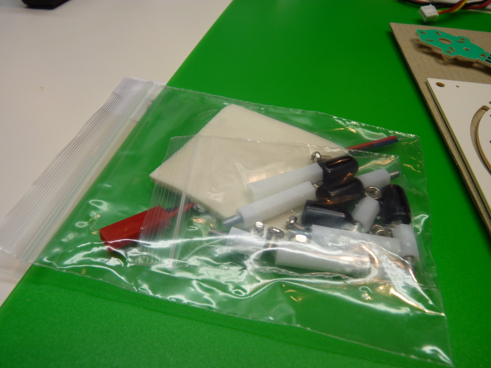
Here's the included hardware. It's everything needed except for the motor mount.
Everything dry fitted together, with the top bolted on.
Here's the leg mounts, assembled and ready to attach.
The shield bolts seem a bit short.
Everything attached, looking from the top.
The fully assembled frame, bolted but not glued.
The motors, motor mounts, and spinners (which won't be used -- see the next step).
(UPDATE: ignore prop information below. see part 2 where I recommend using a hammer to pound the props on.)
Here's the prop... notice the tiny hole. Let's try the prop saver!
You will need a 1mm hex wrench to install the prop saver. Put the big rounded end out.
The motor includes an o-ring to attach the prop. I've had much better luck with theraband prop savers.
The small prop hole doesn't fit onto the end of the prop saver, but if you wiggle the prop a bit it will fit snugly on the end. Don't forget to balance the blades.
To be continued...
Subscribe to:
Posts (Atom)