Wednesday, February 16, 2011

Bay Area UAV Flyers

Hooray, Chris set up a page for local fly/meetup groups.

I've joined the Bay Area UAV Flyers. Flight locations so far:

Ardupilot Mega arrived from uDrones today!

Just got a call from Josh, the assembled and tested Ardupilot Mega has arrived from uDrones today.  This is a pretty big deal thing, as I was a bit intimidated by all the soldering that needs to be done for the plain board version.  What if the board didn't work when I was finished?  How would I tell if it were a problem with my assembly, or something else?[*]  I would hate to turn "Josh's Flying Camera" project into "Mark's Learning Electronics" project!

But, udrones.com to the rescue, who is selling an assembled and tested package including the main board, IMU, GPS, and magnetometer, all assembled, tested, and loaded with code.  Hooray, and thanks to diydrones for the heads-up!

Speaking of diydrones, I met with head-droner Chris Anderson this last weekend.  He lives in Berkeley, and tests at the same places that I fly.  I'll follow up with another post, but I told him about the Arcticopter project, and that I was interested in writing a document oriented to the beginner.

So, onwards and upwards, hopefully to the exact altitude specified!


 [*] which would match 100% my first experience with RC planes.  I bought my first receiver (a Spektrum AR6100E), and spent literally hours trying to get it to bind to the transmitter.  Since I had never seen in real life a bind procedure, I had no idea what to expect, or how to diagnose the problem.  I eventually put a youtube up on rcgroups and asked if I was doing it correctly (they said I was).  The story has a happy ending -- I contacted Horizon, they looked at the video, confirmed I was doing it right, and sent me a replacement unit which I received in two days.

I also had the same experience the time I tried flying my first plane.  It was a foamy I had built using plans downloaded from rcgroups.  It had a lot of problems, and I had no idea if it was something I was doing wrong as a pilot, or something I had done wrong building, or some combination of both!

Cubelets: "smart robotics construction cubes"

A coworker just forwarded this to me, and it's way too cool not to mention here.

Cubelets are a toy robotics kit.  The modular pieces snap together with magnets; different modules do different things.  Their video, for example, shows a robot made of three blocks: battery, drive, and sensor.  Stack them together, move your hand towards it, and it moves away.  Neat!

It's in preproduction, and they've delivered a first batch for people to test.  Their standard kit includes these 20 cubes:

Action Blocks: 2 Drive, 1 Rotate, 1 Speaker, 1 Flashlight, 1 Bar Graph
Sense Blocks: 1 Knob, 1 Brightness, 2 Distance, 1 Temperature
Think/Utility Blocks: 2 Inverse, 1 Minimum, 1 Maximum, 1 Battery, 2 Passive, 2 Blocker

Monday, February 14, 2011

Extending the motor wires

I made a mistake prepping the motor wires with the 3mm bullet connectors.  Unlike a plane (which I am used to), the motors on a quad sit quite a ways away from the ESCs.  So, when I went to wire everything up, there was a several inch gap between the connections.

So, I stripped the shrinkwrap and unsoldered the bullet connectors, and extended the wires.  There were a dozen of the things to do, so I did one first to check for fit, and then did the remainder in a batch, assembly-line style.  I made them a tiny bit longer than they needed, so that we would have some wiggle-room (literally) for the ESCs.  Next time, I'll try making it an exact fit.

I didn't try reusing the bullet connectors... they were kinda messy on the outside after soldering.  I wonder if there's any way to clean solder of lots of pieces at once?  I was also surprised at how heavy a dozen connectors full of lead solder weigh.  I tried using the minimum possible solder on the new connectors.  It made it a bit more tidy as well.  It seems just as strong... I wasn't able to pull it off by tugging at it.

I took photos... partly because I thought it might be useful for someone not super-experienced with solder, but mostly because I thought they would look pretty cool.

Cut all the wires to the desired length, strip and tin the bullet side.  You don't need much solder, since these are being placed in the connector cup. Just make sure the wires are saturated.  One of the previous posts has some details about using the board to hold the connectors.  Strip the insulation so that the exposed wire is just as long as the internal connector cup.

 Nicely attached to the connectors.  I was careful not to get any solder on the outside, which allows 3.5mm shrinkwrap to fit right over the connector.
3.5mm Shrinkwrap on the bullet connectors, ready for the heat gun
Nice looking shrink wrap job, huh?
 Now strip and twist the ends that will be connected to the motor leads.  It will be stripped a bit longer than the connector side, since this will be a wire-to-wire connection.
 Tin the wires.  Notice that we add a bit more of a solder blob (but still not too much; we don't want a big ball of solder in the middle of our wire).  We do the same thing to the motor leads as well.  When the wires are joined, the two solder blobs will be what flows between the wires.  Dont forget to add the shrink wrap before you solder, or you will have to unsolder and do it all again.  On the other hand, maybe that's good practice!
 Here's a set of wires soldered together...
 ... and shrinkwrapped.  Get a heat gun, it really does make a nicer looking connection than using a lighter or any other ghetto method.
 There are tons of techniques for soldering wires together, you can find some really great tutorials on youtube.  I like using an alligator clip to hold the two wires together.  When you heat the wires up, the solder melts, and the jaws of the alligator clip mash the two wires together nicely.

If the solder sticks to the alligator clip, touch the soldering iron to the outside of the clip and it will come right off.  Don't tug, or the two wires will come apart.
 Here's the finished set of motor wire extensions.  Doing them assembly-line style speeds things up a lot and reduces errors.  I wasn't looking forward to doing this, but it wasn't bad at all.  Maybe I'm just getting a bit more used to soldering as well.
Here's the finished result, held in place with blue tape.  Note the extra bit of slack... next time, I'll mount the ESC in its permanent position and try to do it so there's no slack at all.  And by "no slack", I mean "just enough slack so there's no strain on the connections".

Some rcexplorer kkboard dimensions

Mike Grundvig, maker of the AeroFPV aluminum frame, is very kindly going to send us an aluminum mount for the kkboard, and offer that mount in the AeroFPV kit.  He requested we send some dimensions and pics.


David over at rcexplorer sent us these dimensions:
  • hole distances: 45mm
  • distance between two holes diagonally: 63.6mm
  • board: 50*50mm. 
  • exact same size and hole distance as a MikroKopter controller.
Here's our board.

 The mounting holes seem to be about 3mm.

 I just cut a 4 x 3 x 1/8 inch piece of basswood (about the same size as the ardu board) and mounted that to the aerofpv frame.  I was going to be fancy and bolt the kkboard onto the basswood, but I didn't have any non-slip bolts of that size, so instead I'll just use 3M thick double-sticky tape.  That should give a bit of bonus vibration protection as well.


Here's the back of the board.

GoldGuy fixes flex fabulously

Method 1 -- reinforce with 1mm carbon "needle"
  • sharpen the tip of a piece of 1mm carbon rod with 80 grit sandpaper.
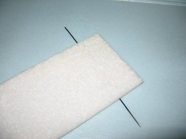
  • force it into the foam, run it all the way through.  no glue necessary.
  • add one at the control horn location and any other place necessary.
  • use the piece like a needle.  thread it all the way through, clip the rod, and you've still got a sharp point to do the next piece.


Method 2 -- embedding carbon crosses
  • Drill hole in 4mm carbon tube, make a crossbar with 1mm carbon rod. Threadwrap and CA.
  • You want to make this an integral part of the wing, not just embedded into a slot.
  • Make the slot with a modified soldering iron.
  • Run a short bead of hot glue into the slot, press the CF into place.
  • Hold flat with a steel ruler until cool.
  • Open the joint, and repeat gluing until the full length of CF is attached.
  • The forced-in CF tube will have caused a bend in the foam.
  • Weigh the wing down on a dead flat surface.
  • Run a bead of hot glue on top of the CF.
  • Remelt the hot glue, making sure you glue the edges of the foam for maximum hold.
  • Use a trim iron to remove any excess hot glue as you go along.

More pics and description at the links.  Thanks GoldGuy!

"Neatness is Lightness." -- GoldGuy at RCGroups.

Building Light...

Superslo28" Build,Tip,Tricks thread!:

Some great tips from tallflyersd at rcgroups on building a light-weight superslow-28. I think a lot of these are generally applicable, so I'm condensing ere. Check out his youtube channel as well!

His 28" plane is 7 oz, and he's going for a 5 oz version as well.

  • Make fuse out of 9mm, rudder, wings and elevator out of 6mm EPP.
  • Use light servos such as Blue Bird 306.
  • Cut a little off the motor mount.
  • No glue or velcro for radio - cut holes and tape in place.
  • Battery pack velcro: 1/4 inch wide, 4 inches long.
  • Shorten ESC wires to both battery and motor.  Makes it more tidy too!
  • Trim any extra parts off of servo and elevator horns.
  • Use 250-350 mAh batteries.
  • DONT OVERGLUE and OVERPAINT.  Airbush will keep it light, keep your designs small.
  • Carbon control rods don't save any weight over Dubro 0.37 micro control rods. [Me: is this true?]
  • Hinges: 1"x3/4" tape on the top of each wing, tailfeathers 3/4" x 3/4", 3 pieces for rudder, 4 pieces for elevator.

test of flikr


;kl;lk;k;;k;


P1000750;lk;lk;;;k

Sunday, February 13, 2011

EasyStar Brushless Notes and Shopping List

Here's what I did to convert the EasyStar to a brushless system.

Andreas recommends the credit card approach for expanding the rudder, and using real hinges to install.  I did that here.


Shopping List:
 CA Glue and Kicker:

The instructions recommend CA (superglue) and CA Accelerator (aka kicker).  You can probably use just about any medium-viscosity super-glue.  You definitely want the kicker.  Don't get any glue on your skin along with the kicker... it gets hot fast, and of course it's glued to your skin!  A lot of people recommend using Goop glue (which is soft and rubbery) for attaching the motor.  Then it's a lot easier to cut out neatly if you need to replace it.
Range Video has two interesting EasyStar products:
  • EZ-Pod: nice-looking no-mod canopy replacement for holding a camera with servos.
  • Outrunner brushless motor mount:  not sure why this is any better than using an inrunner, unless you were planning on swapping motors a lot?
Chris has an awesome aerial video mount here, and a video down at the Alameda Air Station.

Friday, February 11, 2011

KK Board arrived from Sweden!

As mentioned before, the Arcticopter 1 will be driven by a KapteinKUK flight controller from rcexplorer.se.  It's arrived.  Smaller than I imagined, and it comes with free Swedish stamps!  We haven't tried it out yet, but it was nicely packed and shipped promptly.  David (a.k.a dadde86 dadde87 on youtube) has been great,  answering some questions to help us get going.
It came preloaded with the quad-X configuration; New or different builds can be downloaded with the standard ATMEL procedures.

RC Eye Candy

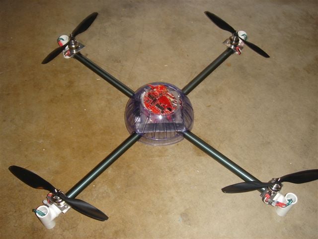
Here are Josh's shots of our first evening's build of the Arcticopter 1 frame. I'll add these to the build log with notes, etc, but I couldn't bring myself to leave any of these unposted.  See how smart I am, to work with a pro photographer on this!

Enjoy, lots more after the break!


Pololu - Micro Maestro 6-Channel USB Servo Controller (Assembled)

USB Servo Controller: $20 assembled.


"The six-channel Micro Maestro raises the performance bar for serial servo controllers with features such as a native USB interface and internal scripting control. Whether you want high-performance servo control (0.25μs resolution with built-in speed and acceleration control) or a general I/O controller (e.g. to interface with a sensor or ESC via your USB port), this tiny, versatile device will deliver. The fully assembled version ships with header pins installed."

Thursday, February 10, 2011

Mikro: A New 1000mm Quad Copter Design

On RC Groups.  Check out the video, it's really smooth!

Mikro sez:  "The whole system is quite impressive. I always thought one needed to have the custom modified I2C ESC's and expensive motors to be able to lift these loads with the stability you'd want for aerial photography. This design proves you don't and it has a lower price point than the other approaches. Thank you VERY much Mike Dammar and Mike Cook (Old Man Mike)!"

Assembling the AeroFPV frame

The AeroFPV frame arrived, nicely packaged.  Overall impression so far: nicely made and beautifully crafted... you know how you ooh and aah when you see a new Mac?  same feeling here!  Everything is tight and precise.  The milled slots for the arms are great.  Well done, AeroFPV guys!

We didn't bother printing the build guide.   Instead, we opened it in two side-by-side browser windows, so we could read the instructions in one and look at the parts illustrations in the other.

We're building this with a KK controller, so we'll deviate a tiny bit from the instructions to make a mount that handles the smaller size board.  The AeroFPV frame guys have requested the dimensions of that board, and are going to make a mount of the appropriate size.

We're going to try running the motor wires through the arms.

Links
Build Notes

I'm not wanting to replicate the most excellent build guide (linked above), so instead of repeating all the text from each step, I'll just put our photos and add whatever commentary seems useful.


unboxing and miscellaneous notes.
  • Use a 1/4 inch nut driver to hold all the hex nuts.  It's a lot faster and easier than using a crescent wrench (although that works with no problem).
  • All the fasteners come in numbered baggies, making assembly really easy. It also makes it trivial to verify you've got all the pieces you need.
  • We lined up everything for the picture... it turned out to be handy when we were assembling as well.
  • If you've got two people working on this thing, it's nice to have an extra set of hex wrenches so you can both be working on attaching the legs, etc, at the same time.
  • The fasteners are stainless steel, very nice.


 motor mount prep.
  • The larger piece goes on top.
  • All nuts go on the bottom.


frame plates.
  • The smaller cross-shaped piece goes on the bottom.  In these pictures the pieces are upside down.


motor mount attachment.
  • Notice how nicely the arms fit in the channel.  It's a precise fit, so if the mounts aren't perfectly lined up you just need to jiggle things a bit to get it all lined up.
  • Here's where a 1/4 inch nut driver comes in handy.
  • The motor goes on top of the bar, prop side up.


arm attachment.
  • Make sure the arm registers against the inside stop and that the big piece is on top.


speed control tray.
  • The drilled-out part of the speed control tray goes on the bottom.  The top part of the tray is flat, and the blue vibration dampeners will stick up.
  • The flat side of the spacer will butt right up to the hex screw on the top frame plate.


motor attachment.
  • Use the screws that came with the kit to attach your motors.  The screws go on the bottom.  This picture shows the motors upside down.
  • We had one motor with a misaligned screw hole.  If you're not getting high-end motors, it doesn't hurt to order a spare.

landing gear
  • The bumps face the outside.  Put it together loosely.  Later you will attach this piece to the main frame, at which time you can get everything nicely lined up and tightened down.
  • Oops!  a bit of a mistake.  The build guide shows both halves of the nylon connector on the inside of the frame.  Thanks to  nanobug in the aeroquad forum for the catch!


controller board attachment
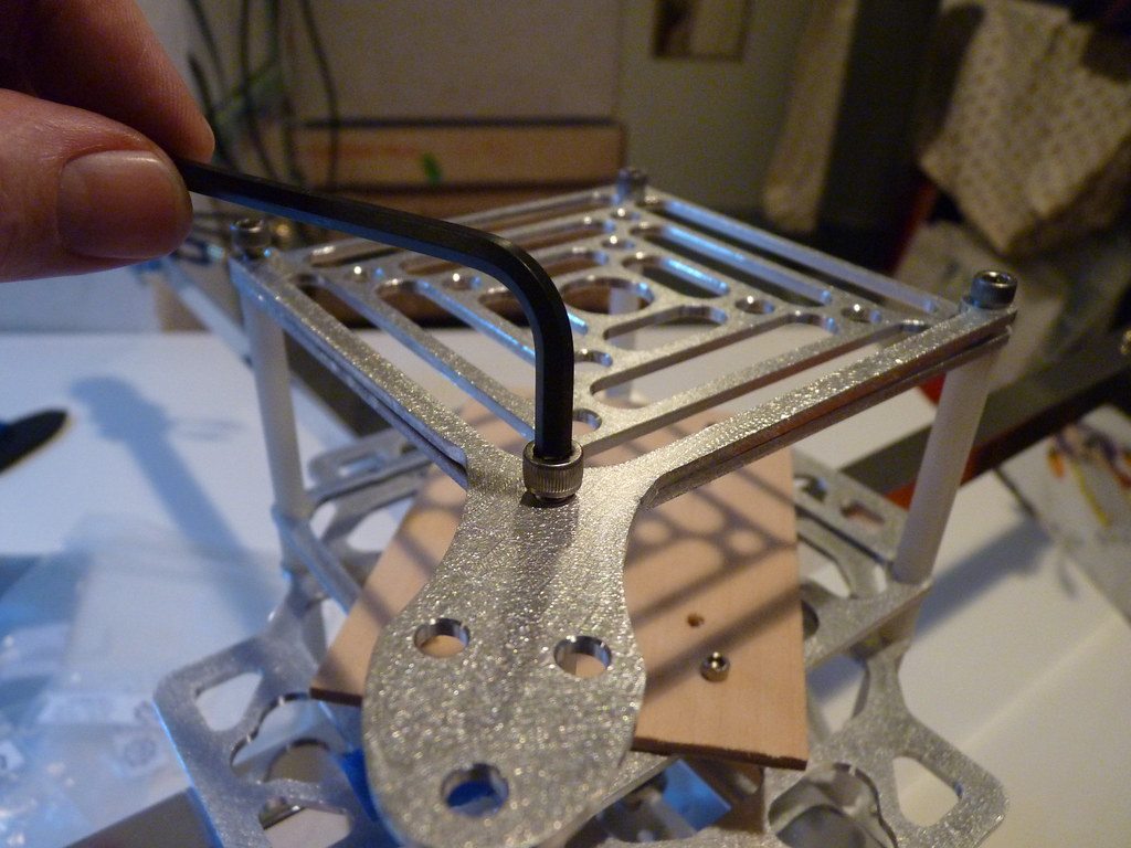
  • The controller board attaches "square" to the frame for a + model, and at a 45 degree angle for an x configuration.
  • The KK controller is a lot smaller than the arducopter board.  We broke off for the evening to think about this, and decided to mount the kkboard on a piece of 1/8 inch wood the same size as the arduboard (3x4 inches).
  • We'll use double-sided thick sticky tape to attach the kkboard.
  • Update: he AeroFPV guys are going to make a kkboard-sized mount and send it to us... hooray and thanks!


  • Because the Arcticopter 1 will be an x configuration, the board is mounted at a 45 degee angle.


battery tray.
  • Attaches to the bottom using the 2 inch nylon standoffs.
  • We had a problem that the battery didn't quite fit in the gap.  We're ordered some 1/2 inch standoffs from Amazon and will attach those for the time being to give us some space.
  • Our 3000 mAh battery doesn't quite fit between the standoff in x mode.  We'll figure out how to balance the battery and attach it securely later.


accessory tray.
  • Attaches to the top of everything.
  • You can screw the camera mount on if you like at this time, since they use the same screws.


skid attachment. z
  • attaches to the battery mount.
  • once you've attached it, straighten the legs and tighten the holders.


 camera mount.
  • The camera mount screws onto the top accessory tray.  I haven't received my gopro yet, but there was a question on one of the forums about how to attach the gopro.  It turns out there's a "gopro grab bag of mounts" that has a mount with the right holes, but the wrong size.  I'll probably just make one of my own.  Future post with details once I get to it.


final view.

The stack looks like this, from the bottom up:
  • landing gear
  • battery tray
  • 2 inch spacer
  • frame plate (bottom)
  • arms
  • frame plate (top)
  • ESC tray
  • half inch spacer
  • controller board tray
  • 2 inch spacer
  • accessory tray
modified stack. z
As mentioned, we were a bit squeezed, so we ordered some half-inch standoffs to add some space in the ESC tray and battery tray. Until then, we just rearranged some of the layers so we could keep going with the power system.  The pieces are quick to shuffle around, so this isn't a headache.


power distribution.z
  • We needed the extra space on the ESC tray because we're using a WAGO connector to distribute power.  We'll experiment with this and see how it goes, but for now I think they're pretty great.  More details in another post regarding power.

A Thing of Beauty is a Joy Forever!
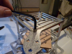
  • It's a nice frame, easy to work with, sturdy, and a good feel.
  • Final steps:  mount kkboard, attach electronics nicely, add receiver.
  • Will it fly as nicely as it looks?  We'll know this weekend!