TL;DR; is that instead of just having full forward/reverse current or not on each winding, the driver can also do things like 90%/10%, 80%/20%, 70/30, etc. current for the two windings to position the motors at angles between the full/half step positions. the actual ratios aren't quite this simplistic, and are designed to achieve something close to constant holding torque and even step spacing, but since the exact angle achieved for any winding current ratio depends on the motor design, and application, it's more or less impossible to get microstep positions that are a precise fraction of the full step angle for all motors/applications. this is mostly OK because 1) you're not making the full step positions any less accurate, 2) you're still making motor motion smoother by taking smaller steps.
1) MEASURE the CG on your plane. Do whatever is necessary to adjust it to 31mm, which is the factory recommended starting point. Do this before you try anything else.
2) Zero your tx trims. If your transmitter allows, adjust the trim-steps to the smallest setting. (Usually "1".)
3) Power-up the plane, but do not engage AS3X. Then disconnect the battery.
4) Mechanically trim the elevator so that it's neutral with respect to the stab.
5) Take the plane up for a flight with the CG @ 31mm & see how it behaves power-off & power-on.
6) If it glides smoothly & doesn't balloon under power, you're done.
7) If it porpoises during the glide and/or balloons under power - add down-trim until it glides smoothly, then zero your tx trim & transfer the tx trim to mechanical trim.
8) Note the degrees of down-trim with respect to the stab. If it's only a few degrees or so, you can call it good - unless you're trying to squeeze every last bit of glide performance out of the airframe that you can get. If you're trying to set a personal UMXR glide record, adjust the decalage accordingly, so that no visible trim is needed for best glide with the CG at 31-32mm. If the plane needs a lot of visible down-trim with the CG at 31-32mm, the decalage is off enough to warrant fixing it or returning the plane & getting a replacement.
Remember that you must re-trim the elevator for best glide whenever you change the CG. That is absolutely mandatory. If you don't, you will simply end up chasing your tail & get frustrated with the process of flight-trimming. When you get it right, you will be rewarded with a plane that glides smoothly & efficiently, and exhibits very little (if any) throttle-pitch coupling under power.See the video below for an example of how the plane is supposed to behave when it's trimmed & balanced correctly, and the decalage is about right. Be sure to turn up the sound, as I narrate during the flight. It's a bit long, but the 19 minutes it takes to watch the entire video will most likely be worth it for those who are new to sailplanes.
Here's another method of fine-tuning the CG:
1) Take the plane up high, trim for level flight @ say 20-25% throttle. Better yet, trim for the flattest stable power-off glide (no porpoising).
2) Enter a power-off dive at a 45-degree angle, then release the sticks, and observe the plane's behavior:
A. Plane pulls sharply out of the dive as soon as you release the elevator: The plane is extremely nose-heavy. Move the CG aft, take the plane back up, re-trim as described above, then repeat the test.
B. Plane starts to dive more steeply (tucks toward the belly) when you release the elevator: The plane is tail-heavy. Move the CG forward, take the plane up, re-trim as described above, then repeat the test.
C. Plane continues on its path: The CG is at the neutral-handling point (often called the sweet-spot), which provides the greatest sensitivity to lift (the plane will indicate weaker lift than it will when it's nose-heavy). A neutral CG also results in the lowest stall-speed & the least amount of drag. But it also makes the plane neutrally-stable in pitch, so it will not self-correct in a dive. Many competition sailplane pilots prefer a neutral CG, but some pilots prefer a slightly-forward CG.
D. Plane starts to gently pull out of the dive when you release the stick: The CG is just slightly forward of neutral. The plane will still indicate light lift (albeit not quite as well as it would with a neutral CG), and it will be more stable in pitch than it is with a neutral CG. Some sailplane pilots prefer this CG position, as the slightly positive pitch-stability makes the plane less-apt to suddenly enter a dive or climb on its own when it gets perturbed by the air currents. The slight loss of efficiency is rarely noticeable to casual sailplane pilots who are not concerned with getting every last bit of performance from the airframe.
Remember that at this scale, moving the CG just 1-2mm is noticeable in flight. Avoid making large changes unless you're sure that the the CG is way off. Also, remember to re-trim for level flight each time you move the CG. This is absolutely critical. Failure to re-trim as described above will negate the entire process.
Also remember that CG is not a fixed number. Move it forward a bit for better wind-penetration on turbulent days, or for increased glide speed on windy days. Move it back to the sweet-spot in calm conditions and/or when lift is very light & you want to stay aloft on the farts of field-mice alone.
If the decalage is correct, you'll end up with the elevator level or close to level with respect to the stab after the above tests. If not - then the decalage is likely off. Which means you'd need to do the decalage test.
Decalage test:
1) Zero your elevator trim on the tx, then mechanically neutralize the elevator with respect to the stab.
2) Take the plane up, but do not re-trim the elevator in flight. This is absolutely critical, as re-trimming the elevator after neutralizing it before the flight will screw up the test & render the results useless.
3) Perform a power-off vertical dive from high altitude, release the elevator stick, and observe the plane's behavior:
A. Model continues straight down: No change needed.
B. Model pulls to canopy: Increase stab incidence with respect to the wing.
C. Model pulls to belly: Reduce stab incidence with respect to the wing.
Adjusting the CG as described above is the next step after verifying that the decalage is correct.
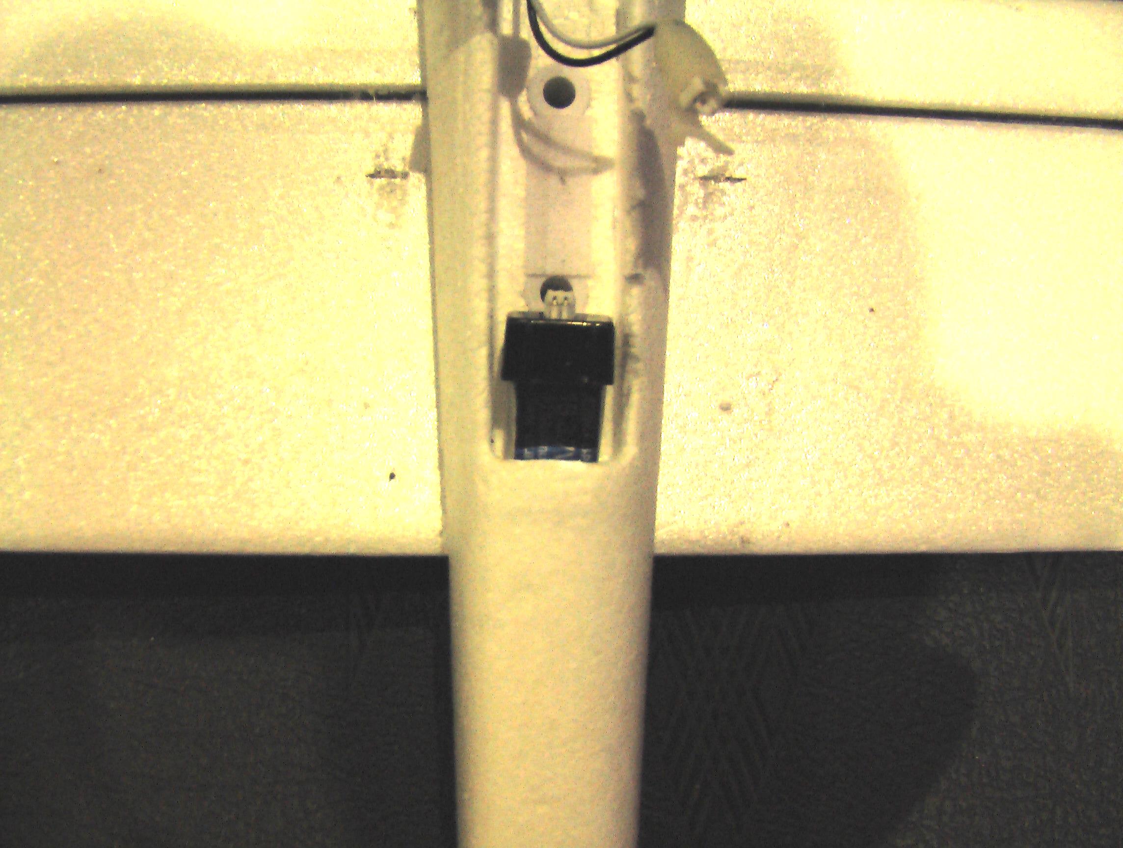
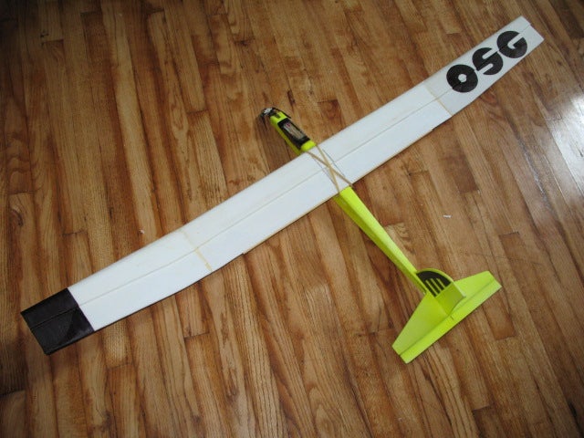
Here's where the batt ends up on mine to get the CG to the sweet-spot for best glide performance & power-on behavior. You can also see the CG 'sweet-spot' marks on the wings:
GoldGuy, the inventor of the NutBall, reveals some NutBall tricks and his propensity for poetry:
1. Next time your out, experience the distinctive sound made by a NutBall. Here's how............
Take it to altitude with the nose up, instantly give it full down and full left. It will flip over and go into a violent but controllable spin. Hear that sound it makes? It's the only model I know that does it. To slow down it's decent, just cut the throttle. To get out of it, just relax the controls, then feed in a bit of up. Cool eh?
2. The snap roll is similar. Flying straight and level fed in some up and then do the same, down and left. If you time it right, you'll get one complete violent snap in an instant. Practice at altitude and when you get it right, do it at eye level for best effect and you'll come out looking like a pro.
Also, in that inverted flat spin mode you can use the throttle and elevator to go up and down. Hold in the rudder the whole time..................throttle back, it will come down, add throttle and a bit more down and it will go up. You can go up and down in that inverted spinning mode as long as you wish.
You will have to move the battery back for a 30 to 35% CG for best flopabatics.
3. Rolling the NutBall is an easy to do and a basic maneuver. Once you've mastered it, the roll becomes the basis for the snap roll, spins, inverted flat spin (complete with sound effects), the inverted 'elevator', both up and down, plus other silly weird stuff.
Rolling is more than just slapping over the rudder stick with the NB, although with models like the Simple Delta, flat and with elevons, that's all it takes to look good. What you want is to practice nice smooth rolls where the speed of rotation is the same throughout the 360 degrees of travel, it can be done almost axel, it's all in the timing and rolling to the left is easier to start off with. Make sure you set the CG at 25 percent to start, you can modify that as you progress, fly the maneuver at a MEDIUM speed at first and pay attention to the amount of movement on the rudder and elevator, not too much (???) is lots. The big problem in rolling the NutBall is that with too much rudder throw it wants to flip over very quickly once past inverted. How much movement is all apart of fine tuning. Having a low wing loading is a big aid in flying aerobatics as everything is much easier to do. If there's too much of a breeze, mount a bigger battery or some lead ballast, keeping the CG unchanged.
So, here's what to do to start off with.....................
Fly along straight and level at a brisk speed, but not full tilt (yet), and just before you enter the roll, add a tiny bit of up elevator to rise the nose, then feed in the rudder nice and smooth and when it goes inverted give it a tiny blip of down elevator and let off on the rudder just after is goes past inverted. What you need to do in the beginning is to form a pattern or tune in your brain. Practice in your shop with the model in front of you, try and picture in your mind what's happening. I learned four point rolls by repeating this to myself as I moved the sticks in the proper sequence and at the proper speed................ta da, ta da, ta da, ta da. It's like a tune in your head and you keep to the timing. Not sure what key I'm in, but it works. Got that from the best 3D pilot I know.
When you go out to practice, by yourself seems best and concertrate on the one thing and do just that.
#4 Here's another easy fun one anyone can do, the 'upright elevator', although it's all down elevator, no up. You'll need a rearward CG for this one, but start off with what you've got to see the difference it makes. Gain lots of altitude and point the nose straight into the wind. Now, hit full up and hold, and kill the thottle at the same time (again, it's in the timing) and use just the rudder to keep it facing into the wind. It should float down like a leaf, and with a low wing loading and a nice breeze you can plop it right down on the wheels. You can do this one inverted too.
Have fun with it.............all it takes is a bit of practice and a little more after that............your starting to look like a pro now...............keep it up
The above Charger doesn't include a power supply. You can use an old PC power supply or laptop power supply if you've got one. If not, this one will do what you need.
- Supports up to 6S LiPO battery packs
- DC IR measurements up to 2 decimal places (cell & pack)
- Independent pack voltage measurement capability
- Large built in LCD
- XT60 Input
- Single balance connector able to run 2S - 6S packs
Install Cura, and add Bob's files to the appropriate places in /Applications/Cura. You should see the Mini as a printer option in Cura, with 100 micron and 200 micron configurations.
# set printhead pids M301 P36.00 I0.012 D72.00 C0.12 L2 # set bed pids M304 P106.56 I0.024 D96.81 # write parms M500 # print parms M503 Setting WiFi M550 SSID
M551 PASSWORD
Interesting GCode
G28 ; home M190 S60 ; Wait for bed temperature to reach target temp M104 S195 ; Set Extruder Temperature target and continue M109 S195 ; Set Extruder Temperature and Wait
Some snippets for init/deinit Start: ---------------------------------------------------------------- G28 ;Home G1 Z15.0 F6000 ;Move the platform down 15mm ;Prime the extruder G92 E0 G1 F200 E3 G92 E0 ----------------------------------------------------------------
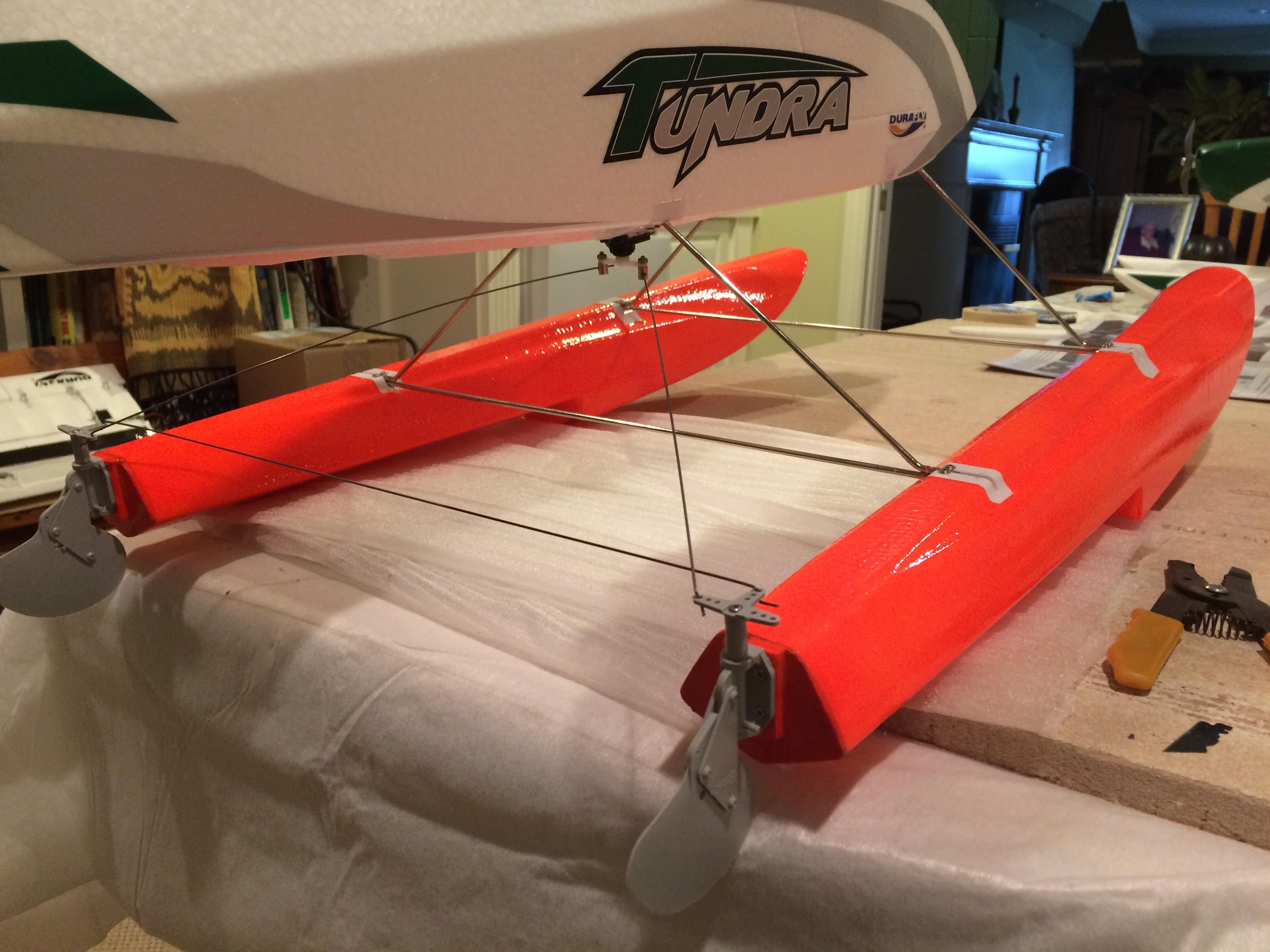
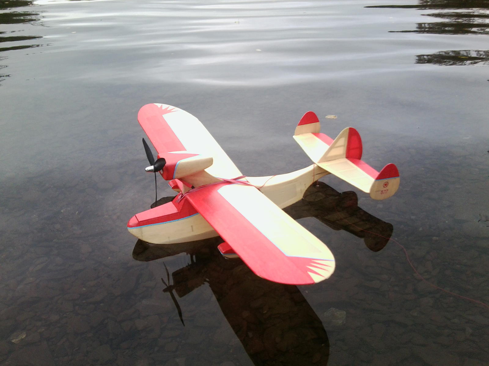
Saw this on RCGroups. This seems a better solution than the stock rudder mount. gravity keeps the Ernst rudders down and will kick up as necessary. I'm not sure of the exact size. Note the pull-pull mechanism connecting to the single servo.
Here's a picture of another plane with the rudders mounted on wood at the back.
Part description is:
Water Rudder .40-.60
ERNST MANUFACTURING INC. ERN155
Due to the limitations of the two-wire method, the four-wire (Kelvin) connection method shown in Figure 2 is generallypreferred for low resistance measurements because it reduces the effect of test lead resistance. These measurements can be made using a DMM, SourceMeter SMU instrument, or a separate current source and voltmeter. With this configuration, the test current (I) is forced through the test resistance (R) via one set of test leads, while the voltage (VM) across the DUT is measured through a second set of leads (sense leads). Although some small current (typically less than 100pA) may flow through the sense leads, it is usually negligible and can generally be ignored for all practical purposes. The voltage drop across the sense leads is negligible, so the voltage measured by the meter (VM) is essentially the same as the voltage (VR) across the resistance (R). As a result, the resistance value can be determined much more accurately than with the two-wire method.
Note that the voltage-sensing leads should be connected as close to the resistor under test as possible to avoid including part of the resistance of the test leads in the measurement.
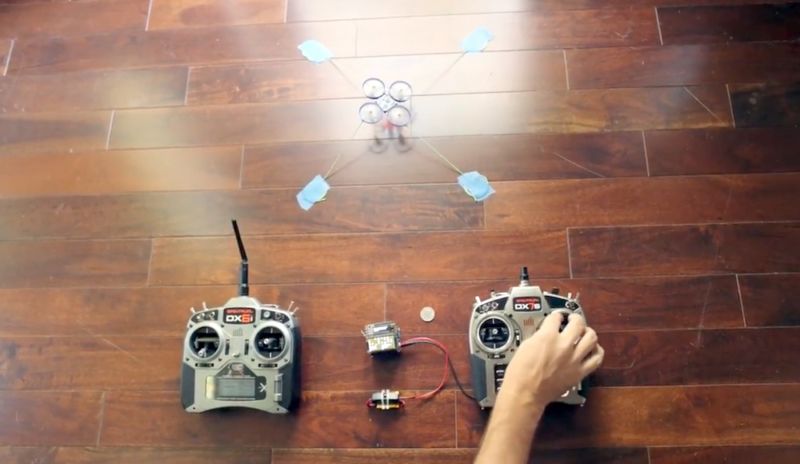
Arduino based game controller adapter for regular RC receivers up to 6 channels.
It acts as an USB joystick, dispatching the channels values read from a PWM RC receiver. Aimed to be fast and responsible, though simple to use with automatic calibration function. It can be useful to play simulator wireless from the computer with your favourite transmitter. Compatible withWindows, Mac, Linux, Android,IOS.
Requirements
The .hex file and the supplied installer is only compatible with Sparkfun Pro Micro, do not try to flash it on other Arduino compatible devices. If you want to give it a go on other boards, then compile from source! Source:http://github.com/gregnau/wireless_rc_adapter
Installer should be easy as double-clicking the install.bat while the Pro Micro is plugged in. Everything is detailed to the screen, so if there is any error you can start investigating
Worth checking before flashing! hex-file checksum: d7065aed90c259e7ef3d8fe3dad3f1d7
Some jumperwires are needed to connect the receiver to the Pro Micro. Below on the picture you can see an example of wiring and setup in details.
Wiring
(it is attached below to the post, i have no idea how to put it here) wiring.png
Manual
The Pro Micro boards usually have 2 leds side-by-side, which are the TX and RX status lights. These are used to reflect the state of the adapter:
On every startup these are flashing twice, then one of them is going off, the other one stays on. This means booted up successfully and ready to play.
But if they stay on, that means the adapter is in calibration mode. The calibration data is loaded and verified during setup,
but if these are incorrect/missing than it goes to calibration mode automatically.
Automatic calibration
Calibration process is the same as everywhere, the sticks, pots, switches on all channels must moved to their extents. Preferably more than once and in slow motion.
The leds are lit
During calibration there is no sending of joystick values to the host, there is no feedback at all, except it is in '#DEBUG_ENABLED' mode. Though in debug mode it's only using terminal to send data, there is no hid interface. While in normal operation after the calibration data is accepted and saved it goes directly to play mode.
Manual calibration
Sometimes it is needed to re-calibrate the adapter, although there is valid calibration data saved. To achieve that just plug in the usb while pushing the attached button. Then everything should be the same as with automatic process.
---
> Still under development so any advice is welcome regarding the code or feedback on use! Only known restriction is the calibration autosave function accepts only if there is 6 working channels calibrated. In case you connect less channels then you always need to push the button to save calibration data.
Michael Melchior has an interesting series of four articles where he reverse engineers a quadcopter, including the radio protocol. It's really good, and he includes links to his code that listens to the radio. As they say, read the whole thing! (Part 1) (Part 2) (Part 3)(Part 4)
Here's TurboParker's excellent tutorial on setting up the UMX Radian. It's probably good advice for all planes. I'm capturing it here because sometimes RCGroups is a bit difficult to search.
I'm a big fan of Julian "Yes I have a personalized flashlight" Ilett. Check out his youtube channel if you're interested in electronics. The "postbag" videos are great if you like hands-on reviews of cheap ebay components.
He's got a two-part video where he builds and then reverse engineers a cheap doorbell kit. It's a really clever design. I learned a lot from Julian's explanation! Check it out and buy a kit if you're interested.
Spent a couple of hours helping make this video, and got two seconds of screen time. According to the film people, that's a pretty good ratio!
And of course always sweet to do something to help the Khan Academy.
Anyways, quite proud to have done a real bona fide bit of aerial camera work.
I'm embedding the YouTube page, and the Khan page is here. If you wanna skip the boring parts and see my two seconds of fame (starting at 0:46), go here.
Transmitter-to-Receiver latency is a much-cited metric when discussing radio systems.
Andy Kunz, a member of the Spektrum development team, wrote a couple of posts going into great detail about how latency is measured and what it means. Because RCG posts get hard to search, I'm capturing them here for posterity.
I've moderately edited from theseposts and a couple in between (quoting people asking questions).
An interesting RCG note from Springer at Model Plane Foam. They're a pretty cool outfit... they asked the manufacturer of Dollar Tree foamboard for a foam more suited to model building.
Model Plane Foam is available from modelplanefoam.com. it is the same recipe as the latest Dow fff, white, no film or printing or perforations. Shipping to AZ is high, but it is still typically less than Depron. Here's the thread with the history and info on it:
Adams says that the dtf formula is different from the Dow formula which is what we get (less the pigment, of course). A grade MPF has a fine skin with almost a rubbery feel to it that is decently dent resistant. A big part of the difference in both stiffness and durability comes from that skin.When the paper is removed the dtf surface is composed of open cells (no dense skin left at all) which is fragile and dents easily. So the difference in strength/stiffness is a combination of factors. Current A grade MPF is running between .2 and .23" thick, on the low side of the thickness spec.
I'm sure that a big part of the cost difference is shipping (I find it is awfully expensive to ship mostly air!), but process may also be a factor, if I understand correctly, Depron is extruded in flat sheets (probably why it has best flatness) wheras MPF and fff are extruded in a different process that has higher throughput, but sacrifices flatness (sometimes - it varies within a run and is one of the parameters we specifically ask them to control better than they do for fff).
As far as stiffness, density, etc. MPF is targeted at 2lb/cu. ft. From what I have seen of depron, it seems like similar density. Depron is stiffer but more brittle, which I attribute to the formula difference. One customer who made 3d plane kits loved MPF for his planes because a crash that would previously result in a bunch of Depron pieces was a non issue for MPF. He was one of those who milled away foam to make a girder structure in the foam sheet so the increased toughness was important.
Got an SQ8 camera to try as a hatcam. It has a nice clip system. I made an adapter out of instamorph, Even if the camera turns out to be a dud, I'm super impressed with how well the instamorph holds on to the brim of the hat.
I'll try it out "for real" soon and report back on image quality, etc. So far not too bad for $20.
I think I need to get a faster memory card though. 1080p carries about 15 FPS.
Some stats: 720p, about 6Mbps, 29.79 FPS; 1080p, a bit less than 15FPS.
The way I've got it mounted now holds the camera upside down. Here's the incantation to flip the image and convert to h.264. The duplicate transpose items aren't a type.
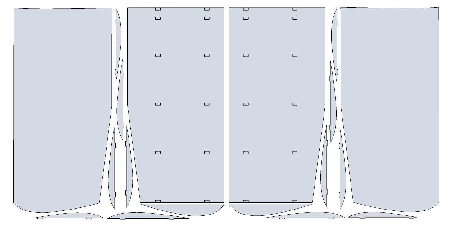
Here's the raw materials for the E-Fly Body. For each body, you will need 3 sheets of foam, 1 carbon tube, and two pieces of steel wire. I think severlthe shipping won't go
Here's a current-sensing module from Sparkfun. It's non-invasive, clamping around the wire carrying the current you wish to measure. I'm planning to use it to watch a particular appliance and see when it's on and off.
My initial plans are to attach it to an ESP8266 (Huzzah breakout), upload the measured current to thingspeak via a local wifi, and watch it from there.
Over on rcgroups, user balsa or carbon shares some hints on making ReadiBoard EZFlys. Check out his videos, you can see the great results he gets.
I make EzFlys out of ReadiBoard, both paper on and paper off. Single layer everywhere except the wing's leading edge will be double layer with the KFm, and the nose will be triple layer with the two nose doublers. For a stronger, faster flying EzFly - I leave the paper on and scotch tape over all the edges. But the exposed paper will be susceptible to moisture. For a very lightweight slow and floaty EzFly , I cut out all the parts and then peel the paper off. I also use lightweight electronics and increase the wingspan to 40" for very light wing loading.
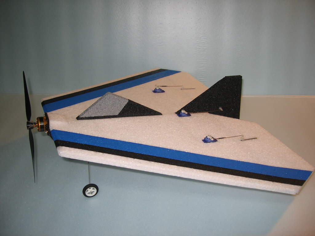
Looks like a nice slow-flyer to build for beginners. Based on the late Dekan's Simple Delta.
GoldGuy Says:
Twenty more square inches than my first 22 incher and one ounce lighter for a loading of 3 ounce per square feet at a 6 ounce RTF weight. It's a 8X22X17 with the elevon hinge line at 3 1/2 incher. Start off with the CG at 5 1/2" and then fine tune to taste. Take your SD to the next level, the SSD will loop, roll, spin, snap, stall turns, harrier, prop hang, torque roll and flies inverted on rails, all this and no pitch sensitivity at any speed. Oh ya, and crazy climbing inverted flat spins the guys call 'the Dilbert' (?????). Build it light, keep it tight.............


%20(1)%20(1).jpeg)
.jpg)