Showing posts with label arduino. Show all posts

Thursday, August 21, 2014

FTDI, VCC, and the Arduino Pro Mini

This project has been the first one where I've used a 3.3V Pro Mini.  There's some important things to keep in mind regarding power input.
  • Power input on RAW can be 3.3V - 12V.  It will be regulated to 3.3V.  Specifically, VCC will be 3.3V
  • Power input from the FTDI connector is not regulated. If you are using a 5V FTDI connector VCC will be 5V!
  • In general you can get by with using a 5V FTDI cable on a 3.3V Pro Mini.  It's out of spec but is generally accepted as working.
  • You can't use a 5V FTDI if you are powering a 3.3V device from VCC!

Here's a workaround if you're stuck with a 5V cable and want to use it to power a Mini that has a 3.3V device on VCC.


Remove the VCC line from the FTDI cable.  Gently lift the plastic tab and the  wire with attached connector will slide out.  If you have an extra single-ping cable protector (take one off a female-female breadboard wire if you've got one) you can insert the VCC connector in there.  You could also use some small heatshrink to cover it.  You could let it go bare, but be careful not to short it out.


Attach the FTDI cable (minus the removed VCC) to the Pro Mini as usual.  Attach FTDI VCC to Pro Mini RAW.

Check the voltage on Pro Mini VCC.  It should be 3.3V, regulated by the Pro Mini.


The Sparkfun product page has this note in the comments:

Q: Are the rx/tx lines 5V tolerant? I want to know if it is possible to program this with a 5V FTDI board, without needing to get an additional 3.3V FTDI just for this board. 
A: Yes, the only difference in the 3.3V and 5V Pro Minis is the crystal and the voltage regulator. Since the FTDI bypasses the regulator the only difference is the speed the run at. The ATMega328 is fine at 5V. Keep in mind if you have 3.3V on VCC and 5V on the I/O pins that is technically out of spec (you shouldn't put more than VCC on the I/O pins), but will probably work as well. Keep in mind that the 5V FTDI will put 5V on the VCC line, so make sure you don't have any 3.3V only devices connected when you do this.

blogodex = {"toc" = ["FTDI", "Arduino"], "idx" = {"ArrBot", "Electronics", "Voltage", "No Hack Too Cheap"]};

Wednesday, August 13, 2014

ArrBot: nRF24L01+ notes

Some random notes.  Pay attention to the orientation of this illustration.  The pins are usually on the other side.

                            pins     pin names         arduino connections
 --------------------------------
| antenna                   2  1 |   (2=VCC,  1=GND)   (2=VCC,    1=GND)
| antenna                   4  3 |   (4=CS,   3=CE)    (4=pin 10, 3=pin 9)
| antenna                   6  5 |   (6=MOSI, 5=SCK)   (6=pin 11, 5=pin 13)
| antenna      crystal      8  7 |   (8=IRQ,  7=MISO)  (8=none,   7=pin 12)

 --------------------------------

//   1 - GND
//   2 - VCC 3.3V !!! NOT 5V
//   3 - CE to Arduino pin 9
//   4 - CSN to Arduino pin 10
//   5 - SCK to Arduino pin 13
//   6 - MOSI to Arduino pin 11
//   7 - MISO to Arduino pin 12
//   8 - UNUSED

Saturday, August 9, 2014

ArrBot: Downloading and Setting Up the Software

The ArrBot software lives here. and is zipped up here.

After you fetch it, you need to install three libraries.  Do this three times in the Arduino IDE:
  • Sketch / Import Library / Add Library
and select each of these folders in turn.
  • ArrHeader
  • ArrServos
  • ArrNunchuck


If you're familiar with installing libraries manually, you can just copy those three folders to your Documents/Arduino/library folder.

Once you have done that, you should be able to build and upload any of the programs in the ArrBot distribution.

blogodex = {"toc" : "ArrBot", "idx" = "Arduino"};


Sunday, June 1, 2014

Arduino Class

 A while back I taught an Arduino class, and friend and coworker Josh Minor snapped some pictures.
 Soaking it in...
 It blinks!
 And another one blinks. It is not a coincidence!
 Preparing to blink.
 Contemplating the blink!
Why does it blink?  Electricity!

Monday, May 27, 2013

RC Control of Canon Cameras

If you've got a CHDK-enabled camera, here's a nice instructable that shows how to control it with an RC radio. It uses an Arduino Pro Mini to interface between the receiver and the camera USB.

Chris A. chimed in in the comment section noting that this functionality is now built into the APM software, and that there is a MAVLink command to trigger the camera shutter.

I have to say, even though as a practical matter I would use the APM to control this, it's interesting seeing the more bare-bones approach in this instructable.

Thursday, March 14, 2013

Thursday Miscellanea

Some nice airbrush tutorials on RCGroups.  Be sure and look at the first three posts.  More here.  And a store-bought checkerboard stencil.


Cheap GPS hackery here. Very interesting, and it can save on some projects.  Ebay searchage for "U-blox PCI-5S" and "GPS Ceramic Internal Patch 1575.42MHz Antenna 20x20x7mm" about $15 combined!


Servo City has some nice pin crimpers.


Arduino Power Management here.  Using the JeeLib to access the Atmel low level sleep functionality.


Friday, August 24, 2012

S107g helicopter control via Arduino

Here's an interesting article by Andrew J. Barry that talks about controlling the ubiquitous Syma heli with an IR LED connected to an Arduino.  Source code included to fly by keyboard!  More discussion at RCGroups.

Saturday, June 16, 2012

Processing/Arduino Serial Communications

The Touche for Arduino project has a nice module for talking between Processing and Arduino over a serial connection. Code is on github.

Wednesday, February 1, 2012

Arduino class notes, class 3

Varieties of I/O devices


Pull-up Resistors


Labs

  • circ-07 buttons.
  • circ-11 relays.
  • circ-05 shift register, multiple LEDs.

Bidirectional Motor Control with Relays
  • one pair of relays (3,4) control motion
  • one pair of relays (1,2) control direction
  • smarts courtesy of JWZ


Interfacing to Computer

  • coming up next week


Friday, January 20, 2012

Arduino class notes, class 1

These are the class notes for a 4-part, 8-hour class Introductory Arduino class I'm teaching.  The class consists mostly of programmers fluent in C, which means we won't have to spend much time on the software side of things.  A few of the people have some hardware experience; the majority don't.  A couple of people are actually experts cleverly disguised as students, helping me out!

We're using the Sparkfun Inventor's Kit and tutorial.  Each student is provided with a kit. I bought one of these for myself last year and thought it was a pretty nice kit. (update:  The new version of the kit is even better.  Onward and Upward!)  After the last class I'll provide a wrapup with any notes regarding what pieces were more and less useful, and what supplemental pieces might be used.

SparkFun Inventors Kit
Preliminary Assignment


Class Breakdown

These are the four areas we'll be focussing on.
  • general electronics -- electricity, circuits, etc.
  • arduino specific electronics -- input, output, digital/analog control, etc.
  • arduino programming and libraries -- C coding, libraries for doing interesting things
  • the big picture -- interfacing and combining the lower-level pieces of knowledge into useful or interesting projects
Topics Covered
  • electrical circuits: much handwaving
  • setting up the boards
  • naming of parts
  • downloading arduino environment
  • running the blink program
  • expanding the blink program to tricolor led
Notes
  • Needed to spend more time on breadboards, how they're laid out, how to complete a circuit with them, what the power lines are used for.
  • The Sparkfun project templates are nice, but don't bother attaching them to the breadboard.
  • Because you won't attach them to the breadboard, ignore the two-pin headers on the corners of the board.  They're only used to attach the paper template to the breadboard.
  • We had one kit that had trouble making a connection -- it never showed up on the TTY list.  It turns out to be a faulty USB cable.  Fortunately this happened to one of our more intrepid students who diagnosed the problem right away.
  • All the other hardware worked with no problem.
  • The colors of the wires have no intrinsic meaning.  You typically use red and black for power and ground, but interestingly the Sparkfun kit has no red or black wires.
  • Cover the software portion of the blink lab first.  It looks like the Arduino people test the boards with the blink program, so when you plug everything in for lab 1 the LED starts blinking before the students do anything.
  • If you have access to the boards before you pass them out, it might be nice to download a null program to avoid this.
  • The wiring diagram for the first blink lab has a wire to the power bus that serves no purpose.  This should be eliminated, since it caused students confusion as to what it was doing (nothing).
Khan Academy Circuit Tutorials

This is homework for the next class.  Be cool, sign up for a Khan Academy account, and register me as your coach! My ID is http://facebookid.khanacademy.org/500063084
Next Week

We'll continue with:
  • more on electrical theory, courtesy of Khan Academy.
  • Ohm's Law <-- we must obey it!
  • current, voltage, resistance
  • Some resistor experiments
and more parts (won't get to all of these, will continue in class 3)
  • switches
  • sensors
  • potentiometers
  • motors
  • servos
  • relays
  • pizeo buzzer
  • serial I/O
and here's where it will get interesting:

  • Combining Input + Output -- the basis of interesting projects!

Monday, January 16, 2012

Adding MP3 to your project

A nice instructable for adding MP3 to your project for about $3.

Basic idea:

  • get a cheap MP3 player.  A Miniclip is about $3 on ebay.
  • open it up. remove the battery
  • power via your project
  • solder some wires to play and pause pads
  • set the output of these line high
  • to "push" the buttons, set the line low for a short time


Monday, January 2, 2012

A whole lot of Arduino and Robotics links!

Getting ready to teach an Arduino class, so have a lot of links prepping for that.  Instead of giving the impression that this blog has forgotten about flying, I'm posting a bunch of miscellania here.

Timer Stuff
  • timer1 library. This library is a collection of routines for configuring the 16 bit hardware timer called Timer1 on the ATmega168/328. There are 3 hardware timers available on the chip, and they can be configured in a variety of ways to achieve different functionality.
  • SO query with a couple of answers.
AVR Programming
Arduino Tutorials
Clickwheels and Diskdrive Spinners
  • some forum post.
  • Instructable: HDDJ: Turning an old hard disk drive into a rotary input device (video)
  • code: Interfacing › HDDJ:hard drive as scrollwheel/turtable-like input
LarryBot
Motors
DS1307 RTC Module
Calculators

Wednesday, December 28, 2011

DS1307 Real Time Clock

Here's some notes on a real time clock.  I'm not so much interested in knowing the time, but it uses I2C to communicate and I've been looking for something relatively simple to try I2C.

Tuesday, November 29, 2011

Getting started on Arduino: what to buy and where


Andreas asked me about getting an Arduino development board, and this is what I told him, based on about a year's worth of experience.

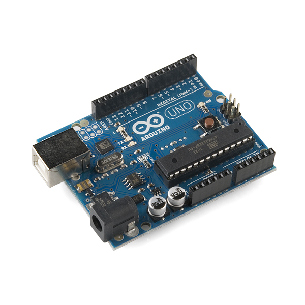
Uno

It seems the industry standard for standalone boards is the "Uno", which uses the ATmega328.  If you see a web page mentioning the Arduino Duemilanove, it's probably pre-dating the Uno.

    http://www.sparkfun.com/products/9950
    http://www.sparkfun.com/products/10356


I bought the Sparkfun Inventors Kit, which was a good way to get started. It has the Uno and pieces for various projects.

    http://www.sparkfun.com/products/10173

The best feature is this nice project book, which is worth checking out in any case.  It's a good introduction to the software as well as the hardware.

    http://www.sparkfun.com/tutorial/AIK/ARDX-EG-SPAR-PRINT-85-REV-10.pdf

Ardweeny

I got the Ardweeny too, which is a pretty neat little system, and awesome for $10.  For a lot of projects, an Ardweeny with a breadboard will do everything the Uno will do for 1/3 the price if you're comfortable with the soldering.  It was one of the first "real" projects I soldered and I didn't have any problems with it.


    http://solarbotics.com/products/kardw/
    http://eastbay-rc.blogspot.com/2011/11/ardweeny-tiny-little-arduino.html

FTDI Adapter

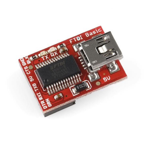
The Ardweeny needs an FTDI adapter, which plugs into a USB cable.  If you're messing around with other Arduino projects like the MultiWiiCopter you will probably have one already.  If you get an Uno, you just need a standard USB cable.

    http://www.solarbotics.com/products/50512/
    http://eastbay-rc.blogspot.com/2011/10/ftdi-and-avr-cables.html
    http://eastbay-rc.blogspot.com/2011/11/attaching-ftdi-connector-to-arduino.html


Clones

My friend and coworker Mark VandeWettering (also the proprietor of brainwagon.org, which you should be reading if you're interested in Arduino things), has mentioned that he's using the OSEPP Arduino clones from Fry's.

    search for OSEPP at Fry's

DealExtreme carries some clones as well.  Radio Shack is selling genuine Arduino products at about the same price as Sparkfun.  It's nice to see them getting back to their electronics tinkering roots.

ATmega2560

To get the ATmega2560, it seems the choice is pretty limited.  It seems that most people's projects fit in the ATMega328 space, so there's not the broad variety of boards in various configurations.  Or perhaps it's just a matter of time?  In either case, avoid the ATmega1280 unless the price difference is worth not having the extra 128K of memory.

    http://www.sparkfun.com/products/9949
    http://www.frys.com/product/6745685


Or, even buy one from diydrones.com!  I think the main downside of this one is that you have to solder the headers yourself.  But it could later be used with an Oilpan and have another complete Ardupilot Mega system.

    http://store.diydrones.com/product_p/br-ardupilot-01.htm


Bits and Pieces

For electronics pieces, Fry's or http://www.goldmine-elec.com.  Get the pieces outlined in the inventors kit above, or if you have a specific project in mind follow the instructions for that.  Get a few small breadboards.  Nothing kills your enthusiasm like having to disassemble and reassemble every project when you want to show somebody something.

My Recommendations

  • If you're an absolute beginner like I was, get the Inventor's Kit.
  • If you're comfortable soldering and want to save quite a few bucks, get one or two Arduweenys and some breadboards.
  • If you're familiar with electronics but don't want to solder, get an Uno.
  • If your project requires an ATmega chip, you don't have many options other than the ATMega2560.
  • Get some extra breadboards.  Goldmine has some cheap ones.
  • Get some extra parts -- resistors, LEDs, etc.

If I had to do it all over again, I think I would get an Ardweeny
and a couple of breadboards.  Then you can keep the wiring all together,
and move the Ardweeny between boards.  (plus random resistors, leds,
etc)

Saturday, November 26, 2011

Ardweeny -- tiny little Arduino

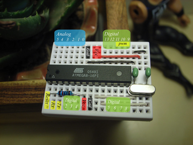
Here's the Ardweeny from Solarbotics.  It's an Arduino system based on Kimio Kosaka's One Chip Arduino.  I got it partly to have a small, cheap Arduino for breadboarding, and partly to practice soldering on a real project.  I'm going to use it to write some code to understand the AT interrupt driven timer.  It will conveniently hang off my laptop nicely without the size and weight of the Uno board, and provide a second processor type to force dealing with the hardware differences.

Here you can see that it's soldered to the top of the ATmega328P.  You can see one pin with much less solder than the others, but it's firmly connected to the chip.  I'm not sure which is better.  If you have an opinion let me know in the comments.
To program, you need an FTDI adapter.  Note that there's a tiny "-" on the board that lines up with the BLK connector.  The Ardweeny can be powered from the FTDI adapter.  It has a reset button and an LED on pin 13, so you can run a standalone blink program!


Here's a shot showing all seven (!!!) components and the pin names.  To program, choose Duemilanove/328 in the Arduino environment.  I'm really impressed with the parsimony of the design.  I think on a future page I'm going to go through each of the seven components as a learning exercise and document what each one does.  


Saturday, November 19, 2011

an Arduino sketch for transmitter tuning


One heachachy thing of dealing with quad is the need to plug the quad into the computer and run the quad tuning software in order to fiddle with your radio settings.  That wouldn't be so bad, except that I fanatically remove the props whenever I do this, which of course means you  then have to turn around and put them right back on.


So, I put together this quick Arduino project to read and display the PWM values from the receiver.  This has allowed me to spend a lot more time fiddling with the often inscrutable menus of the Turnigy 9x and making sense of them.


I made these connection wires to reduce the clutter of having six full three-wire servo connectors.  One end has a male connector and connects to the Arduino; the other end has a female pin and connects to the signal pin of the receiver.  The standard connector goes to an ESC and battery and provides power to the ESC.  I think the Arduino has enough power that it could be used instead.


From the Arduino environment, click the Terminal button and you'll see this output. Nothing fancy, but it allows accurate fiddling with transmitter controls.


This version of the code uses pulseIn(), which nicely does the right thing but suckily does it very slowly.  It's fine if you're just printing out the values, but if you were wanting to do some real control work in between reading the signals, it wouldn't work very well.

#include "WProgram.h"

#define NCHAN (sizeof(chan)/sizeof(chan[0]))
int chan[]={2,3,4,5,6};
int val[NCHAN];

void setup()
{
  int i;
  for (i = 0; i < NCHAN; ++i)
    pinMode(chan[i], INPUT);
  Serial.begin(115200);
}

void loop()
{
  int i;
  for (i = 0; i < NCHAN; ++i)
    val[i] = pulseIn(chan[i], HIGH);
 
  Serial.println();
  for (i = 0; i < NCHAN; ++i) {
    Serial.print(i+1);
    Serial.print(": ");
    Serial.print(val[i]);
    Serial.print("    ");
  }
  //delay(20);
}


Here's some code that uses interrupts to get the timings.  This would be useful on an Arduino Mega, which supports interrupts on six pins.  If you don't have a Mega, you've only got two pins so you're better off with the code above.  There are two other problems with  this code:
  • micros() returns a value which is rounded to a multiple of 4 microseconds, totally unacceptable for tuning radio PWM signals.
  • digitalRead() is very slow and can be made much faster.
I'm going to keep working on this approach, and I'll update later when I've got something to show.  I'm also thinking of making a GUI using Processing.

// reading a PWM signal using interrupts

int pin = 2;       // arduino pin number
int intrnum = 0;   // interrupt number, 0-5 for mega, 0-1 for others

volatile int width;  // width of most recent signal
volatile unsigned long start;  // start time of rising signal

// myisr -- interrupt handler
void myisr()  
{
  unsigned long now = micros();
  int val = digitalRead(2);     // are we high (meaning pulse just started)
                                // or low (meaning pulse just finished) ?
  
  if(val == HIGH) // ascending edge, just save off start time
    start = now;
  else // val == LOW, descending edge, compute pulse width 
   width= now - start;
}  

void setup()  
{  
  Serial.begin(115200);  
  pinMode(pin,INPUT);  
  attachInterrupt(intrnum, myisr, CHANGE); 
}  

void loop()  
{  
  Serial.println(width);
  delay(10);  
}

Thursday, November 17, 2011

Attaching an FTDI connector to an Arduino

 Here's how to hook up an FDTI connector to an Aduino card.  You need one of these when you're programming an Aduino that doesn't have a USB connector.  In this case, it's an Aduino Mini mounted on a MultiWii Paris board.

The FTDI connector plugs into the six pins on the top of the card. You don't need to care about the pin names, but note the BLK and GRN labels.


 Plug a mini USB cable (technically a "USB 2.0 Mini Type B 5 position")  onto the FTDI card and attach it to your computer.  Your computer should load the correct driver.

The FTDI connector is not keyed, so it's easy to attach it backwards.  Nothing bad will happen, but it won't work. There are BLK and GRN labels here as well.  Line up the labels with the Arduino and make the six pins are going into the six sockets.


Your software will have some menu for picking the serial port and baud rate.  On my windows box it's COM6, and on my Mac it's some odd name with "USB" in the middle.

BTW, I don't know what BLK and GRN stand for.  I'm assuming it's "black" and "green", and that some ancient connector used wires of those colors.  In any case, all modern FTDI connectors are cards, and they're all labelled with BLK and GRN.

Wednesday, February 9, 2011

an Arduino product idea

an Arduino product idea

One problem I have with building arduino projects is that I had to take them apart when I started the next one.  I solved this of course by getting some extra breadboards.

But, now I have the problem that I've got a couple of projects, but they're a bit of a hassle to rewire to the arduino board when I want to use them.  I've got the connections written down, but it takes some time and if I make a mistake then it's a pain to troubleshoot.

I know, basically I'm a spoiled software guy.

So, here's two ideas that would make this a bit easier:

Idea 1: Header Extensions

Development cards like the Uno have four sets of  has four sets of header pins (is this what they're called?  the ones you stick your wires into) -- two with 8 pins, two with 6 pins.

It would be nice to have a set of labeled extension headers.  The wires from the breadboard would be inserted into the header, and the header would be inserted into the header on the board.  Some kind of marking or coloration for orientation purposes would be nice.

That way, connecting a project would consist of just connecting the headers, and it would be easy to swap between projects by just swapping out the headers.  It would be clever if the header was easy to write on (e.g., not black)... then you could write the project or file name that needed to be loaded for that breadboard.

It seems you could make your own out of the breakaway female headers, but it would be nice to be able to buy a bag of these.  If they were custom-made, they could even take the header gap into account, and you would only have two header extensions per project.


Idea 2: Header Jumpers

This might be problematic in that it would make your breadboard too big.  Instead of a a header for holding your project wires, all project wires stay on the breadboard.  You then make 6 and 8 wire "extension cords" with a header on each end.  You specify the top 16 rows on the breadboard are for the header jumpers, and connections on your breadboard go to the BCDE holes on the breadboard.  The A holes (lol) would be for the jumpers.

Again, you could make these with the female headers, and custom pieces could reduce the number of jumpers down to two.

So what do you think?  Am I once again looking at a totally solved problem and making everyone roll their eyes in embarrassment?  Let me know if you've got a nice solution for this!  And if this idea happens to make you rich, send me a set, OK?

Friday, December 17, 2010