You need to calibrate two things when you're setting up your 9XR -- sticks and voltmeter.
Both are in the radio setup menu -- Click the left arrow to get there
Sticks and Pots -- setup menu 5 will give you a three-step process to calibrate the sticks and pots. Don't over-stretch the sticks, just move them along the axes for the full range of motion. Be sure and center the pots by moving the blue notches to the topmost position.
Battery Voltage -- if you have a multimeter, you can calibrate the radio voltage display on setup menu 4. Most of the screen displays internal register settings and is used for debugging, but the bottom item is used to calibrate the voltage. Attach a voltmeter to your battery, and match the radio's voltage level to that of you voltmeter. Back on setup screen 1, you can see the voltage alarm level. For LiPo batteries, 9.6 is a good value.
Here's some quick pictures showing how my current 9x modules fit into the 9xr. This is the FrSky module with whip antenna. This is the module that I anticipate using the most, so I'm happy to report that it's a perfect fit and the antenna is nicely positioned. Laying the radio down flat isn't a problem.
Here's the original FlySky module, the one you have to unsolder from the 9x when you first get it. Case fit is good. As with the 9x, it's painful to see the weight of the case resting on the antenna, although as a practical issue it doesn't seem to present a real problem. I used enough epoxy to patch a battleship, so I'm not too worried about it. I possibly might replace this module with a store-bought FS TM002 module, which has a profile similar to the FrSky module.
Here's the FrSky with the patch antenna. Super-happy with how it contours to the case.
The odd duck in the bunch is the OrangeRX DSM module. It's a tight fit in the case, so I use my pocketknife screwdriver to release one of the tabs (update: fit has loosened up, so no problem now). The module align properly, so there's no stress on the Tx pins.
I'm not sure why HK positioned the antenna connector the way they did, but it's not in a good position. The radio basically pivots on the antenna. I'm not too concerned about this, since I plan on getting the 9xr DSM module whenever it comes out. (update: I'm still using the module, and it's continuing to work well. No problem with the odd antenna position!)
Sean stopped by with a few of his latest improvement to the Hugo. First up: Ardupilot Mega! It flies nicely with the default settings.
Also very nice, an external power switch for disconnecting the battery power.
Here's a closeup of the APM 2.5 holder. It's really nice... the unit fits into the holder snugly, the GPS unit screws onto the top, and the receiver velcros onto the bottom.
And a sonar unit has been added. It was an old Sparkfun unit that Sean had sitting around, model number unknown. We haven't configured the APM to use it yet.
The USB cable fits nicely in the ventilation gap. Sean's going to figure out something to attach to the cable to stiffen it up so it will be easier to plug in without removing the cover.
Here's a complete shopping list. (update: this post used to have "telemetry" and "no telemetry" options, but FrSky discontinued their non-telemetry line. I've updated the post to remove links to the discontinued non-telemetry items. Note that even if you get the telemetry-enabled units, they work just fine without using the telemetry.)
First, you need the "no module" version of the transmitter. Get the "Mode 2" (left hand throttle) unless you know otherwise.
Here's two good LiFe batteries. The 2100 has a bigger capacity, but IMO the 1500 is fine for many hours and a better value. That's the one I've used before. You can also use just about any 3S battery if you've got a spare, so you can consider this "optional but recommended." I've been using a 3S 500 mAh and it's been great.
Here's the telemetry module with one receiver, and extra receivers. The module comes with one receiver. Get enough receivers so you have one installed on each model.
Here's the telemetry display screen. It plugs into your module. You need to figure out a way to attach it to your transmitter. Most people attach it to the transmitter handle.
Here's a better whip antenna and a patch antenna. The higher the dB, the better range, and the more directional. Neither of these are very expensive, so they're probably worth it if you're doing FPV or autopilot stuff.
[shopping note: all the above links have an affiliate code which gives me a small credit when you use them, at no cost to you. Some people are bothered by the concept of affiliate codes... if you are one of them, please feel free to remove the affiliate code!]
If you've ever seen video stabilization that works by shifting the frame around, there's a good chance it was stabilized by Deshaker for Virtualdub.
Virtualdub runs on Windows, but I think I might try it out and see how Deshaker works on a couple of my videos. Here's a sample from some Apollo footage. They could put a man on the moon, but they couldn't get him to hold his camera still!
Here's some notes to go along with the tutorial/video for er9x mixing. Some people have said that they thought er9x was more complicated than traditional Tx software, but in many ways I think it's simpler.
Here's a few examples that should cover most of what you need to know to make good use of the mix screen, with accompanying video tutorial. (longer version to be uploaded later)
Mixing a Stick to a Channel
This is the simplest mix you can make. Here's Channel 1, mapped 100% from the rudder (the "source"). The "+" is just a redundant note that it's positive 100%; all percentages are shown with the sign.
CH01 +100%RUD
Set this up, and you'll see the servo attached to channel 1 moves with the rudder stick.
The default 4-channel model definition is nothing more than the four sticks mixed to the first four channels.:
CH01 +100%RUD
CH02 +100%ELE
CH03 +100%THR
CH04 +100%AIL
Mixing a Stick to Two Channels
Now let's do something that's not especially useful in a practical sense, but will be handy for this tutorial. We'll map the rudder stick to two output channels.
CH01 +100%RUD
CH02 +100%RUD
Moving the rudder stick now moves the two servos attached to channels 1 and 2. In some of the following examples, we'll modify channel 2 and leave channel 1 unmodified as a reference.
Reversing
There's a reversing option on the Limits menu, but it's not really necessary. We'll reverse channel 2 by changing the +100% to -100%.
CH01 +100%RUD
CH02 -100%RUD
Now the two servos move in opposite motion.
Reducing Rates
Change channel 2 to +50%.
CH01 +100%RUD
CH02 +50%RUD
Now the two servos move in the same direction again, with channel 2 at 50%. Of course, you could have a reversed lower rate throw by making the percentage negative.
HALF and FULL: Confusing yet Powerful Switch Controls
In order to do anything with switches, we'll use the HALF and FULL inputs. By themselves, they don't do much of anything. Let's channels 1 and 2 to to the sources HALF and FULL, respectively:
CH01 +100%HALF
CH02 +100%FULL
This results in both channels 1 and 2 being output at a value of 100%. Not particularly useful, so let's mix in the GEAR switch to both of these. Keep the default Multiplex setting of ADD.
CH01 +100%HALF Switch(GEA)
CH02 +100%FULL Switch(GEA)
Now we see the channels acting like switches. As we toggle the GEAR switch, we see channel 1 switching between 0% and 100%; channel 2 switches between -100% and 100% (just as we typically want most switches to behave for real).
So, what's happening? Unlike a stick which varies smoothly from -100% to 100%, HALF returns either 0% or +100%, depending on the switch. Likewise, FULL returns either -100% or 100% (the exact value can be modified by the Weight: parameter, but we'll just use 100% to keep things simple).
So, with the GEAR switch specified, the channels output -100% and 0% respectively when the switch is off, and both output 100% when the switch is on. To reverse any of the switches, just select the switch name that starts with "!", such as "!GEA".
Setting up a Switch
So, the standard way to set a simple on/off toggle switch is to use the FULL input. For example, to map the GEAR switch to channel 5, we would do this:
CH05 +100%FULL Switch(GEA)
Note that you can specify a delay and a speed in seconds. The speed is especially nice for things such as flaps and landing gear, since you can get a smooth scale operation.
Mixing a Stick and a Switch ("throttle enable")
Now let's mix a stick and a switch. As a practical example, we'll set up the THR switch to enable the throttle stick. If the THR switch is off, the throttle stick is ignored. This is a good safety feature; when you're plugging in your batteries or carrying the model before you've unplugged your batteries, you won't have to worry that the radio will bump your chest and spin up the prop.
To do this:
Map the throttle stick to the output channel, as covered above.
Specify the THR switch.
Set the Multiplex parameter to REPLACE
The Multiplex parameter can be one of ADD, MULTIPLY, or REPLACE. We specify REPLACE so that when the THR switch is off the output value which would normally be specified by the stick position is replaced by -100%. So, no matter what the stick position, the throttle can't be activated.
CH03 +100%THR
R -100%FULL Switch(!THR)
Combining Multiple Mixes ("dual rates")
Finally, let's look at what we need to do to set up dual rates. This is pretty simple. You can add multiple mixes to the same channel. The switch specifies which mix takes effect (it can actually be a lot more sophisticated, but we'll cover that later). So, this mix:
CH01 +100%AIL Switch(AIL)
+80%AIL Switch(!AIL)
follows this logic:
If the AIL switch is in the normal position, map the AIL stick at 100% to channel 1.
If the AIL switch is in the toggled position, map the AIL stick at 80% to channel 1.
The nice thing about er9x is that you can use a single dual rate switch to manage multiple channels. You could repeat the above lines for the elevator and rudder channels, both of them specifying the AIL switch.
But Wait, There's More!
There's quite a bit more that can be done with er9x mixing, but this covers most of what you need to know. If you're interested in seeing some more, drop me a line!
Lynxmotion sells Aurora 9 gimbals. "these gimbals feature high sensitivity, 8 ball-bearings, and adjustable tension. You can enable or disable self centering on both axis and enable ratcheting on the Y axis." Somebody mentioned they can be fit onto a 9x by removing a pair of tabs and soldering the wires.
Servo City has pin crimpers at a pretty good price.
I've been chatting with Sean Headrick of aerotestra.com and he brought over his latest thinshell model, the Hugo to fly. It was pouring down rain, but no problem! Everything but the props are enclosed in the body, including the motors. There's an interior shelf that holds 2 3S 2750 batteries. Sean gets about 20 minutes of flying around (not just hovering) with this.
The units look really nice, and are pretty light. The frame is 440 grams. It's two halves are permanently bonded together, and each arm has a hatch for accessing the motors and ESCs. There's a top shelf in the center for the flight controller, receiver, and any other electronics. I'll be helping him with some testing and flight controller selection/tuning.
As a bonus, we did some crash tests. Quite sturdy! The last crash took a prop off and pulled a motor loose; Sean's got a new double-cup design that will strengthen up the motor mount.
Here's some videos... flying around in the rain, and then crashing the unit to see how much of a hit it could take. To best see the rain, watch in HD!
The mounting tabs were designed to fit on a Gaui 330x frame. I used micro servo mounting screws to screw the shell together. I made a cutout for the "ABC" status LEDs but I missed the "TX/RX" LEDs. I might incorporate it in the next iteration.
Motorhead has released a new version ("R3") of the EzFly. It moves the motor forward and has an extended nose, both features which make it easier to get the CG forward.
More details to follow, but some quick notes on what we needed to do to get things up and running. Got up to the suggested first steps, having an application capture video from the ar.drone front camera and do facial recognition. Images were fed out through a node.js server, which I thought was a pretty clever idea. I'm so happy in the picture coz it took about an hour to figure out how to get the image displayed. If you're in node.js, serve it up in a browser!
In case you can't puzzle it out, the circled object is Andreas' face, as detected by Open CV. Detection parameters were set to "boyish good looks" of course!
So, we're on track for the droneolympics on Saturday! Andreas is working on a PID package which looks pretty good so far. I was pretty happy with our progress... we basically started on Wed and last night was the first time we had an ar.drone to work with.
Here's a video of the first test flight, running the example ardrone program.
Following is some blabbage on what I did to get the software installed and running on a mac. After spending 30-40 minutes trying to figure out how node.js packages work, I ended up hardcoding paths to everything... I'll try and fix that later.
In which we close out browser windows which have been naggingly left open...
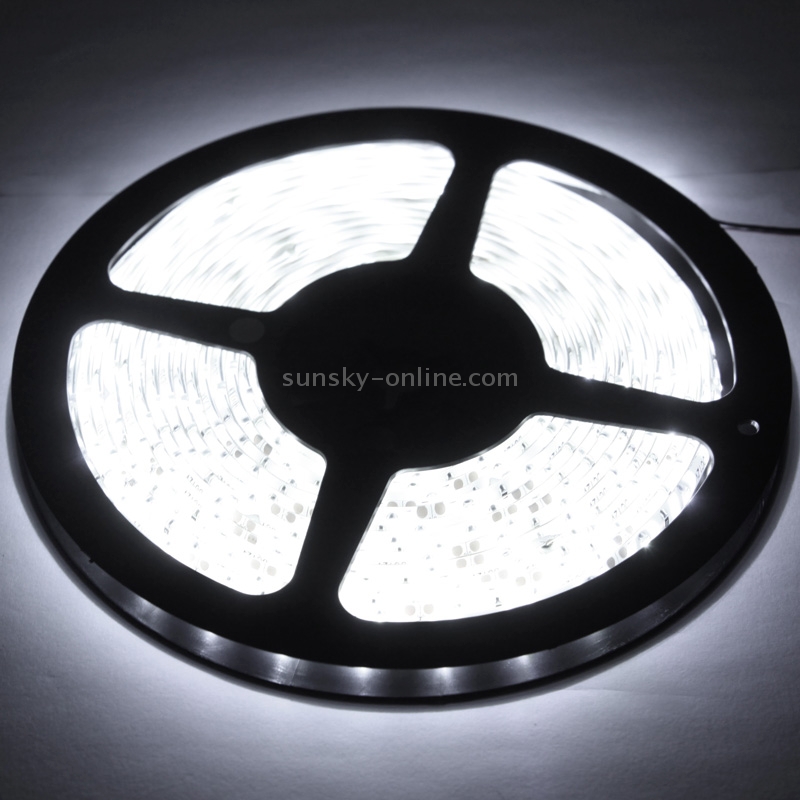
Sunsky has good prices on LEDs. In particular, they carry ropes with 60 and 120 LEDs/m. They've also got an LED controller for under $3.
Nifty swappable joysticks on a small Tx. I've been wanting to fiddle with a tank-like controller for an arduino ground unit, but keep getting stuck on the asymmetric sticks. I keep hoping to find a supplier of 9x sticks!
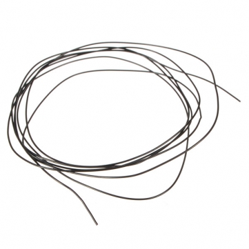
Banggood has some stranded 32 gauge wire in short lengths for $1, including shipping.
Lemon Rx (what a name!) has a DSM2 compatible Rx that has a UART and looks pretty nice for hooking up to projects with a real CPU. Connection is 9600/8N1, and provides stick positions at 50 Hz with a string like this:
[0x13][Ail][AUX][Gear][Ele][Thr][Rud][0x13]
where each value is an octet between 100-200. More details at the link.
There's a PPM port too!
A nice idea for homemade nanoquad motor mounting. And check out the handmade MultiWii FC!
Servo Magazine looks interesting and is recommend by Chris.
Literally, a hangar. Jim Smith of 3D Hobby Shop sold him a plane, and as part of the deal was flown over for some lessons and a demo. FedEx 2nd Day Air shipping cost? A cool $5k. Lots of nifty pics and the rest of the story over at Giant Scale Forums.
My favorite bit? Besides a foamy wing with (presumably) one's self-portrait, the fact that even a prince with his own hangar has to charge his batteries on some overloaded power strip!
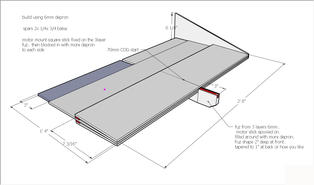
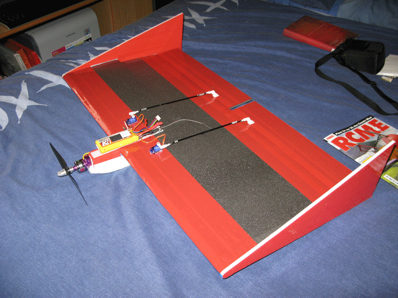
The Nifty, by Dave Reap. 32'' with 6mm depron, 24'' with 3mm.
"The nutball is one of the best fun designs Ive found, I think suitable for beginers and great fun for more advanced fliers...I always plug the big ones, and have more than a few now..A 36" KFm4 is my latest build and I love it.. This plank will fly steady ..check the circuits in the middle part of the video.. but it will not self right itself like the nutball does, and it does not have the fantastic slow speed harier like stability. The plank will stay in the attitude you put it, which means you have to fly it all the time, but it does not give you any problems because its so smooth in what it does..vTo fly this you need to be ok with flying ailerons and elevator, and past the need to have the stability that a nutball gives you.."
The 48'' Albatross and smaller 36'' Pelican are both designs of the ever-awesome Lee of CrashTestHobby.com. Check out the videos on the RCG thread.
"The Albatross offer many possibilities for newer flyers or advanced flyers who want light weight FPV, night flying, indoor flying, slope soaring, aerial photography, and flying in small parks where low noise levels are needed. No one is going to complain if they don't know you are flying."
Here's how to bind a DSM{2,X} transmitter and receiver. This applies to both Spektrum and OrangeRX units.
Safety First: Remove your props. If you screw something up, your motor could unexpectedly spin up at 100% power. That's an uninteresting problem to resolve.
Setup
Remove props.
Power off Rx, Tx.
Make sure ESC is plugged into the THR port of the Rx.
Plug bind plug into Rx bind port. Polarity does not matter.
Binding
Power up plane. The Rx LED should fast blink.
Move Tx sticks into desired failsafe position. Most importantly, make sure THR stick is at lowest position.
Press and hold Tx bind button.
While keeping Tx bind button depressed, power on Tx.
While keeping Tx bind button depressed, wait for Rx LED to go solid.
Release Tx bind button.
Power off Rx.
Power off Tx.
Remove bind plug from Rx.
Testing
Power on Tx.
Power on Rx.
Controls should be operational Fiddle with sticks and adjust Tx settings appropriately.
Testing Failsafe
Adjust throttle so that motor is spinning.
Move sticks so that control surfaces are deflected.
Power off transmitter.
Motor should stop spinning. Depending on your Rx model, the control surfaces will either stay in place or return to the failsafe positions set while binding.
Power on transmitter. Stick control should resume.
Range Testing
Attach the model to the ground.
Move away 90 feet.
Press and hold the Tx Bind button. This puts your Tx into reduced power range test mode.











.jpeg)