Thursday, March 15, 2012

Step Down PSU, 3.3v, 5v, 9v, 12v

Ordered this from hobbyic.com and stashing the docs, such as they are, here.  They note: "Do not power 1W video transmitter"

Wednesday, March 14, 2012

Zephyr II glued up!

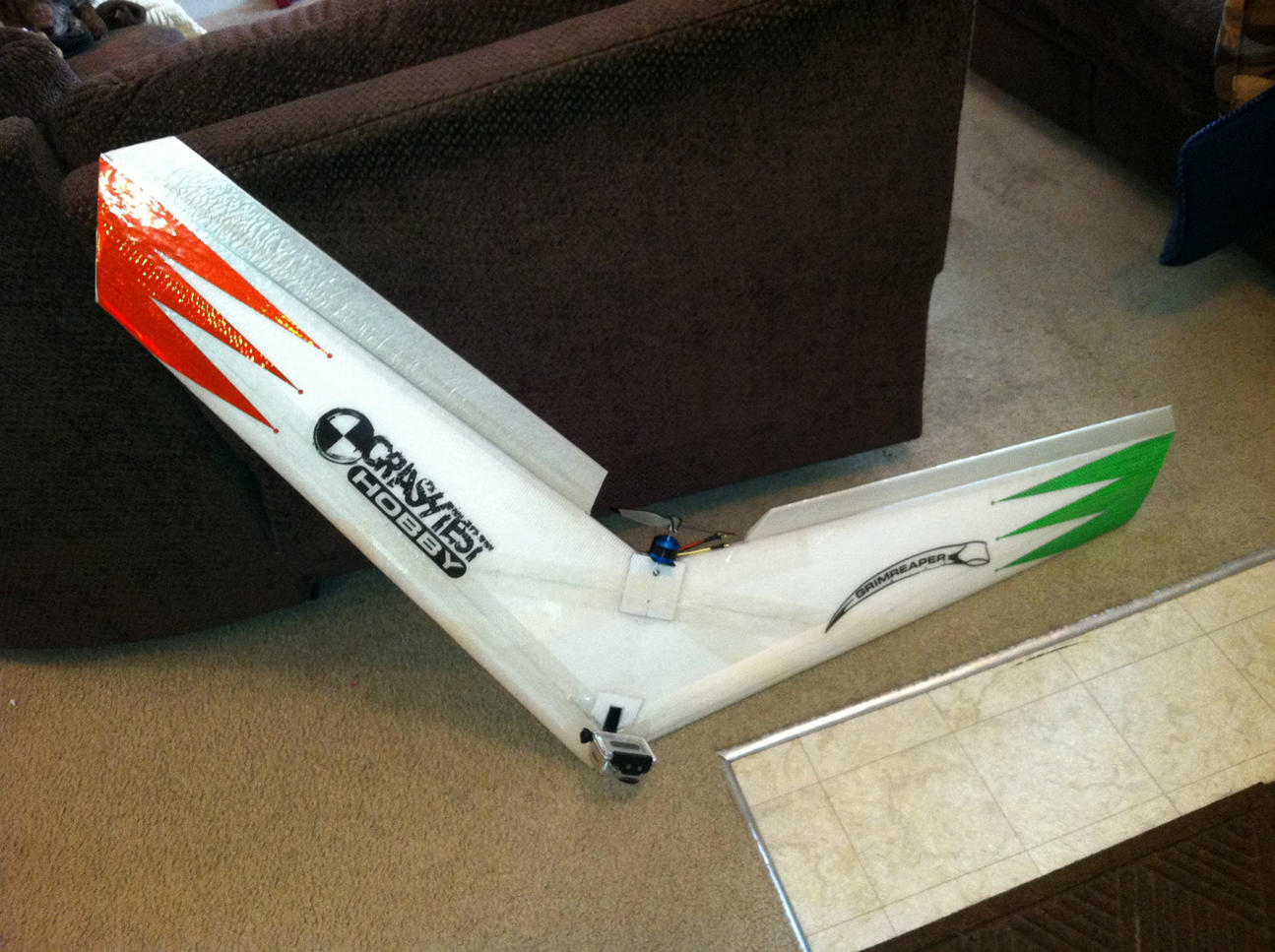
Got the body glued up... wasn't quite sure what I was doing with the 3M 90, but it went not too badly.  That stuff is sticky.  I got some on my hand and had to wait for the next day for it to wear off.
I didn't get good coverage on the tips, but a bit of epoxy seems to have set things right.
I followed Chris' video for the motor mount installation.  It worked well.  I used a skinny hacksaw blade, so the motor mount was a bit of a tight fit and caused some cracking of the foam.  A bit of epoxy set things right.  Next time, I'll use a fatter blade, or make extra passes with the skinny blade to hollow the slot out a bit more.

Outdoor Screen Mod -- prototype

I heard Tridge mention in a presentation that they had solved their outdoor PC screen viewing problem by removing the back of their laptop.  I couldn't find any other references on the internet to this kind of procedure, so I thought I would give it a try and report on how it went.

tl;dr:  seems to work well, waiting for a sunny day to take it out and try it.

This laptop has a non-functioning battery and not enough memory to run the ground station, but seemed to be a good candidate for an outdoor viewing enhancement.  The basic idea is to cut the back off, and let the sunlight enhance the LCD backlight.  It was pretty straightforward on this Dell.  Pop the rubber caps off the bezel and remove the screws.  Jiggle the bezel and it will come loose.  Remove the screws holding the screen in.  They are all perpendicular to the screen.  There are some side-screws that hold the mount onto the screen itself, but you don't need to loosen them.  Once everything is off, you can fold the LCD down and away from the back panel.  Cover everything with blue tape and saran wrap.  I used a dremel with a large cutting wheel to cut a rectangle out of the back panel.  Be careful not to let the metal dust get into the laptop.  Reattach the LCD and the bezel.  Later I'll epoxy a plexiglass panel to the back -- now I've just got it covered in tape.


Here's a picture of the back when the laptop is powered on.  You can see the control wires, etc.


Here's a front view.  It seems a bit darker than usual (because it's not getting reflected light?), but still quite good, especially for an older model laptop.
Waiting for the rain to go away for testing, but holding the laptop up to an incandescent light makes everything brighter.  You can see the control wires shading the display.

More later, including a walkthrough, but for now this looks promising.

Saturday, March 10, 2012

Zephyr II bay measurements

I didn't see these online anywhere, so I made a few quick measurements, close to at least a couple of mm.  If there's more than one depth measurement it's front/middle/back.

            length  width  depth
    front bay  152    110  35-40-38
    back bay    70    110  20-15
    servo       53     40  20


Multiplatform XBee Configurator


The most direct way to configure simple parameters on an XBee is to use the "AT" command set.  For more advance things, you have typically needed to download the XBee configuration tool, which inconveniently in some cases runs on Windows only.  Moltosenso is multiplatform tool that might be useful.  The base edition is free; features like scripting are available in the premium packages.

Moltosenso's description from their web page:

moltosenso Network Manager™ IRON is the cross-platform answer for the users of Digi International® X-CTU™. The same functionalities are now available on Microsoft Windows®, Linux® and Mac OS X™ operating systems.

Thanks to a snappy and totally free GUI, moltosenso Network Manager™ IRON is able to grant:

  • get/set of the parameters of Digi International® modules plugged to the PC, both in API and AT mode;
  • get/set of the parameters of Digi International® modules remotely addressable;
  • an effective graphic test for RSSI parameter, especially tailored for XBEE™ modules;
  • firmware upload (local and - where available - remote) for many supported Digi International® modules.

eCalc propCalc -- Propeller Calculator!

Courtesy of the most awesome brosius85, here's a great power system calculator that seems pretty comprehensive.  It has a large selection of motor data, nice charts showing the power curve, and warnings when some parameter is out of whack.  Thanks Brosius!!

Wednesday, March 7, 2012

Notes for KapteinKUK PI Tuning Guide


How to recognize different gain settings.

Too low P-gain: @0:01
- hard to control
- easy to over correct

Correct P-gain: @0:45
- easy to control and fly

Too high P-gain: @1:22
- oscillates rapidly
- gains height easily
- hard to control height
- oscillating sound from the motors

Too high I-gain: @1:49
- same as with too high P-gain, but oscillates with a lower frequency

Single axis tuning on a string @2:08

Setup: @2:08
- set yaw PI-gain to zero
- set Roll/Pitch I-gain to zero

P-gain too low: @ 2:19
- slow and imprecise stick response
- easy to turn by hand

Increased P-gain: @3:09
- sharper stick response
- harder to turn by hand

Good P-gain: @4:08
- sharp stick response
- slight oscillations when releasing the stick
- hard to turn by hand

Too high P-gain: @5:05
- scillates rapidly
- oscillating sound from the motors

Good P-gain, too low I-gain: @5:38
- moves back to center when stick is releaseddue to gravity
- easy to move by hand over long time

Good P-gain, good I-gain: @6:17
- stays in position when stick is released
- very hard to move by hand over long time

Good P-gain, too high I-gain: @6:57
- oscillates, but with a lower frequency than with a too high P-gain

Monday, March 5, 2012

A nice UAV radio transmitter

Here's a controller for a huge moving truck, as seen on a clip from Extreme Machines.  I'd like to have something like this (not quite so meaty of course!) for controlling a drone.

In particular, the Arducopter software has a lot of variations (e.g. simple compass control) that would be nice to map onto a clearly-labelled, easy-to-hit button.

Are there any RC transmitters that feature a row of buttons or switches like this?  If so, I'd be interested in hearing about it!

Friday, March 2, 2012

New Superfly!

 Put the new Superfly together... it has the 5 inch center section.  Will try to maiden it tomorrow.
Saw a note from somebody on rcgroups, mentioning that they had attached the canopy with velcro.  I'm going to give it a try.

More later!

Thursday, March 1, 2012

Kicking off the Zephyr II build!

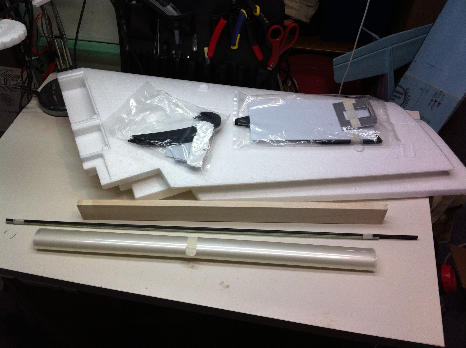
 Well it looks like our favorite uncle in Hong Kong is ALMOST ready to send a gift to me, so it's about time to get my Zii build kicked off.  Here's a couple of pictures of the Zii kit out of the box.  Andreas loaned me his can of 3M 90 spray adhesive, and I picked up a can of flat black spray paint.  Here's everything as they came out of the box.  The wings were wrapped in foamy wrap.
 Here's the (optional) gopro kit and skids come in one bag.
 The motor mount, battery compartment cover, and wing tips come in another bag.  There's a bit of cutting dust from the wing tips, so it seems like they're CNC milled?  Chris has a nice video about attaching the motor mount that you should watch before starting to build.
Left to right, the (optional) covering, spars (2 black, 4 white), and balsa ailerons.

Sunday, February 26, 2012

Sky Stick -- what to do with your Busted Hawk Sky

When it's crashes its final crash, what can you do with a smashed Hawk Sky? Turn it into a stick of course!


Saturday, February 25, 2012

Art of Electronics book

Here's where I got my copy.

Open Source Lipo Charger

Very Nifty! Paul Asselin has an open source hardware design, based on the Microchip MCP73831.  You can download the schematics and Eagle files directly. He also sells a kit or completed unit.

Sony 600TVL Super HAD board camera for FPV

As recommended by Bruce, who notes "I am not sure which lens I have on this camera -- I requested a 3.6mm lens but the box says 2.8mm. I will check and update the review accordingly."


BidProduct Crimping Tools

Will any of these work for balance plugs?  Must investigate!  Many more on the page.  PS, this is the site with all the micro receivers as well.

Zephyr II launching notes

From Chris:


Launch with 3/4 throttle to full power.
Align elevons to match wing top foil contour out by the wing ends
and give 3 to 5 clicks of up.  If you align with bottom you will
stall it as soon as you launch and naturally try grab for elevator
up.This will also cause the roll out during the tip stall, its not
an issue with lateral balance , its you stalling it by too much up
input and no airspeed.
Once you get it flying and trimmed power on then do a few passes
under good power and chop the throttle to see if she rises or drops
once power is removed.  If it does either than your thrust angle
is off ,and will need to adjustment.
Launching it with no power and holding it back by the prop opening
is just asking for finger slicing issues.


Friday, February 24, 2012

X468 Flame Gear Camera Mt For GoPro

Atlanta Hobby is carrying this nice looking underbody multicopter GoPro mount.  250 grams, roll and tilt.  Uses HS-55 sized servos. $110.

Monday, February 20, 2012

Stencils for Cloverleaf Antennas

chatch15117 @ RCGroups has a link with stencils for constructing cloverleaf antennas.  Each frequency has its own stencil.

Monday, February 6, 2012

XBee thinks it's a Mouse on Windows...

Here's a problem I had when connecting the XBee to Windows:

  • Plugged in xtremebee USB.
  • Kept getting behavior as if the right mouse button was being pressed.
  • APM could not connect over XBee link.
  • Opening the "Devices and Printers" control panel showed that Windows 7 was thinking the xbee was a mouse.


I looked at various settings to see if there was a "this is not a mouse" button.  I didn't change anything, but it seems to have fixed things.

John Church figured out the problem and the cure:

  • It happens when the APM side is powered up before the PC side.
  • When the USB is attached, Windows sees data coming in over the serial link.
  • Windows comes to the (stupid) conclusion "this must be a mouse!"
  • Fix: power up the PC side USB XBee before powering up the APM.

Wednesday, February 1, 2012

Arduino class notes, class 3

Varieties of I/O devices


Pull-up Resistors


Labs

  • circ-07 buttons.
  • circ-11 relays.
  • circ-05 shift register, multiple LEDs.

Bidirectional Motor Control with Relays
  • one pair of relays (3,4) control motion
  • one pair of relays (1,2) control direction
  • smarts courtesy of JWZ


Interfacing to Computer

  • coming up next week


Monday, January 30, 2012

Slope Soaring with HZ Champ

rcgroups user Goldentaco has a great video of slope soaring a Champ near the Berkeley Marina:


He notes:

Out flying today and found out the Champ can Slope Soar. I was able to run for over an hour on a 160mAh 1s. Throttle for launch or getting out of trouble.
and:
The soaring took place over near the Bulb in in I guess what you could call the Golden Gate Fields' North lot...where the beach access is for dog owners. You couldn't see in the video but it's the pathway coming down from the upper parking lot hill. There is a cliff facing the SF Bay that slopes from nothing on the North end ( right hand side of the video) to about 50 or 60 ft towards the South end. Cliff is about 100yds long where I was flying, then the road I was standing on and another cliff about 20 ft tall behind me so I could soar where the video was shot or loop around behind me as long as I was about 20 ft off the deck ( to avoid turbulence) and get some lift from that "cliff face" too. 
The "Lift Zone" was about 20 yds upwind to 10 yds downwind of the cliff face and up to 10 yds above my head. Not terribly big but like flying in the corner of a football field. You can see it lose alt. near the end of the video that' the edge of the upwind "Lift Zone". 

Gonna have to try  this! 

Wednesday, January 25, 2012

Arduino class notes, class 2

Microcontroller Circuit Model

  • inputs wired to microcontroller
  • outputs wired to microcontroller
  • microcontroller reads inputs, does some processing, sends some output
  • different approach than "traditional" electronics
  • e.g. a button does not complete a circuit to light a lamp, but instead signals the microprocessor that the button has been pressed;  the microprocessor then turns on the lamp
  • Makes circuits much simpler -- cookbook examples of wiring inputs and outputs to the Arduino are often all that is necessary.

Labs

  • circ08 - potentiometer.  circuit diagram is confusing, it says "to pin 13 then to pin 9".  That means use pin 13 for the first part of the lab, and in the second "making it better" part of the lab use pin 9.
  • circ04 - servos.  two parts, sweep and knob input.

Errata

Rod Bogart notes a correction on lab CIRC-03:

    Note: There is an error with CIRC-03. Omit the 10K resistor and
    hook pin 9 directly to the base of the transistor.

All Class Notes

Tuesday, January 24, 2012

Sunday, January 22, 2012

DIY FPV Goggles Update

 Part 1 here...

Here's the current state of the DIY goggles.  The distance to the screen seems about right for use either with or without glasses.
 Here's the view from the inside.  The screen has a resolution of 320x200.  It was $21, and looks about like you'd expect for that price. If it seems like a viable solution, I'll order a better screen.
Here's how it's attached... It was pretty straightforward.  I was going to make a slot down the metal strap so I could vary the distance easily, but this distance seems to work pretty well.

Next steps:  make a lightproof cover, figure out how to attach the battery and wiring, make a convenient connector to the receiver.


Friday, January 20, 2012

Arduino class notes, class 1

These are the class notes for a 4-part, 8-hour class Introductory Arduino class I'm teaching.  The class consists mostly of programmers fluent in C, which means we won't have to spend much time on the software side of things.  A few of the people have some hardware experience; the majority don't.  A couple of people are actually experts cleverly disguised as students, helping me out!

We're using the Sparkfun Inventor's Kit and tutorial.  Each student is provided with a kit. I bought one of these for myself last year and thought it was a pretty nice kit. (update:  The new version of the kit is even better.  Onward and Upward!)  After the last class I'll provide a wrapup with any notes regarding what pieces were more and less useful, and what supplemental pieces might be used.

SparkFun Inventors Kit
Preliminary Assignment


Class Breakdown

These are the four areas we'll be focussing on.
  • general electronics -- electricity, circuits, etc.
  • arduino specific electronics -- input, output, digital/analog control, etc.
  • arduino programming and libraries -- C coding, libraries for doing interesting things
  • the big picture -- interfacing and combining the lower-level pieces of knowledge into useful or interesting projects
Topics Covered
  • electrical circuits: much handwaving
  • setting up the boards
  • naming of parts
  • downloading arduino environment
  • running the blink program
  • expanding the blink program to tricolor led
Notes
  • Needed to spend more time on breadboards, how they're laid out, how to complete a circuit with them, what the power lines are used for.
  • The Sparkfun project templates are nice, but don't bother attaching them to the breadboard.
  • Because you won't attach them to the breadboard, ignore the two-pin headers on the corners of the board.  They're only used to attach the paper template to the breadboard.
  • We had one kit that had trouble making a connection -- it never showed up on the TTY list.  It turns out to be a faulty USB cable.  Fortunately this happened to one of our more intrepid students who diagnosed the problem right away.
  • All the other hardware worked with no problem.
  • The colors of the wires have no intrinsic meaning.  You typically use red and black for power and ground, but interestingly the Sparkfun kit has no red or black wires.
  • Cover the software portion of the blink lab first.  It looks like the Arduino people test the boards with the blink program, so when you plug everything in for lab 1 the LED starts blinking before the students do anything.
  • If you have access to the boards before you pass them out, it might be nice to download a null program to avoid this.
  • The wiring diagram for the first blink lab has a wire to the power bus that serves no purpose.  This should be eliminated, since it caused students confusion as to what it was doing (nothing).
Khan Academy Circuit Tutorials

This is homework for the next class.  Be cool, sign up for a Khan Academy account, and register me as your coach! My ID is http://facebookid.khanacademy.org/500063084
Next Week

We'll continue with:
  • more on electrical theory, courtesy of Khan Academy.
  • Ohm's Law <-- we must obey it!
  • current, voltage, resistance
  • Some resistor experiments
and more parts (won't get to all of these, will continue in class 3)
  • switches
  • sensors
  • potentiometers
  • motors
  • servos
  • relays
  • pizeo buzzer
  • serial I/O
and here's where it will get interesting:

  • Combining Input + Output -- the basis of interesting projects!

Wednesday, January 18, 2012

Update: Night Vapor Batteries


 Here's an update on my lightweight Night Vapor batteries.  I tried ordering some 50mAh cells, but they were out of stock and I got tired of waiting.  So I went ahead to try making some more 70mAh batteries.

Here's the 1S lead soldered onto the cell.  Notice the lead is a lot shorter than previously.
 That's because I got some liquid tape, and didn't have to leave enough room on the wires to put shrink wrap.
 I used a piece of craft stick to daub the liquid tape onto the exposed tab and solder connection.
 Here's what the final unit looks like.  The liquid tape seems to cover pretty well.

The battery doesn't fit into the Celestra charger as is, because the leads are a bit too short and the cell is a bit too wide.  Using a 1S extension solves things nicely.
And it's certainly light enough... Flying the Night Vapor smoothly I was able to get 17 minutes on this battery, about 4mA per minute.  I was impressed!

Update:  this connector is a "Molex PicoBlade (grid: 1.25mm)"

DIY FPV helmet, Part 1

I'm having problems fitting FPV goggles, coz I wear glasses.  So, based on an idea from Bruce, I'm going to try making my own ghetto version by attaching a video monitor to a welding helmet.

Here's the helmet I'm using. It was about $16 from Amazon, including shipping.
 Here's the welding glass cover pieces removed.  Now there's just an empty frame in the welding helmet.
 If I'm able to focus closely, I'll be able to attach the video screen right to the helmet.  This will be convenient coz I'll be able to flip it up.

I don't think I'll be able to get the monitor that close to my eyes, though.  I'll experiment to see the most comfortable distance with and without glasses.
Here's the headband.  It fits well and can be snugged up comfortably.  I think it might be better in this respect than commercial FPV goggles.
 Here's the head size adjustment screw.  There's also an adjustable strap that goes over the top of the head as well.
 And it's stylish!!  I'll take the inventory tag off, but I'm not sure how much it will help.  I'll also consider cutting the lower part off so my mouth is not covered.  It will make it easier to talk, and possibly keep my breath from fogging the inside of the display.
 Here's the 3.5 inch monitor I'm using for the first test.  It's the cheapest monitor on DealExtreme.  Resolution: 320x200, 12V.  It's not bad, but about what you would expect from a $22 monitor.
Here's how I'm thinking of mounting the monitor on the helmet. I'm thinking I can screw my hatcam on top as well.

Part 2 here...

Monday, January 16, 2012

ScrtSqrl's EasyStar outrunner mod

Cheap and easy way of mounting an outrunner on an EasyStar. Basic idea: cut 30mm off of a small medicine bottle and use that as the mount point.

SMT overview

Looks easier than I thought!

Adding MP3 to your project

A nice instructable for adding MP3 to your project for about $3.

Basic idea:

  • get a cheap MP3 player.  A Miniclip is about $3 on ebay.
  • open it up. remove the battery
  • power via your project
  • solder some wires to play and pause pads
  • set the output of these line high
  • to "push" the buttons, set the line low for a short time


Sunday, January 15, 2012

Upgrading Assan GA250

Meng says:


if any people want send the old GA250 back,just do it. here is our address:
ASSAN Electronic Control Tech. Co., 
ADDRESS11F, Block A, Chongqing Business Incubator For Overseas Returnees, Erlang 
No.77 Kecheng Road, Jiu Long Po; Chongqing 400039, China.
Tel: +86-23-86502455 / 86502466

Saturday, January 14, 2012

Aeryon Scout used to help guide tanker to Nome

Nice looking quad, the Aeryon Scout, used to survey the harbor in Nome following 27 ft snowfall.  The Internet claims it runs about $30k - $50k.  More here.

Interesting Laminating Idea


Here's a nifty idea from fnfishcore on rcgroups.
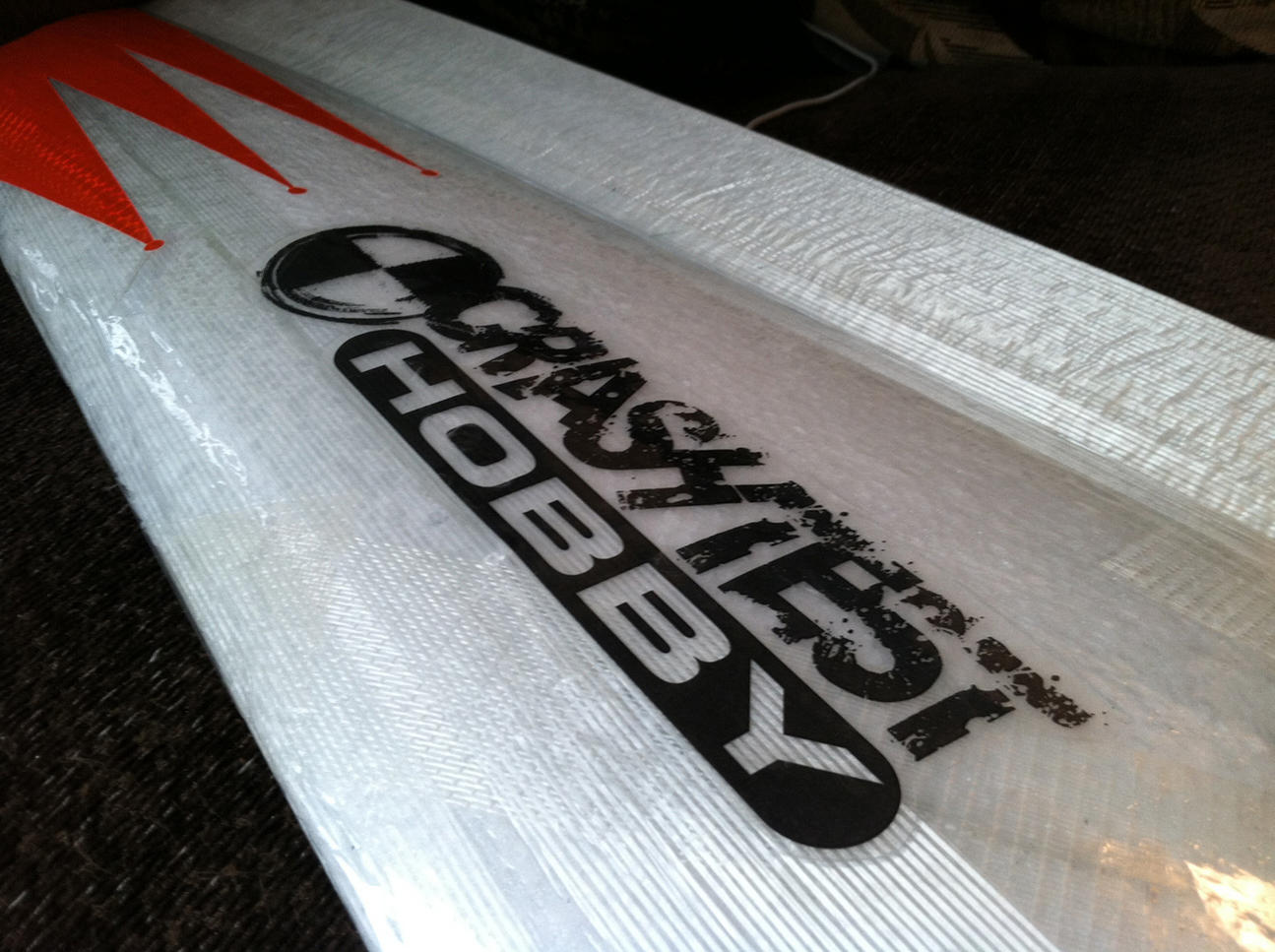


Decorate your plane by printing an image on laser transparency film and putting it under transparent lamination.

(hmm, some weird blogger formatting going on here, hope everything shows up properly)

FPV equipment ordered from RangeVideo


Going to try two different Tx/Rx systems:

1.3GHz video Rx/Tx.  This requires a ham radio license, upcoming!


5.6GHz video Rx/Tx
Camera

not yet ordered.  will use gopro until I figure out which model is best.

Goggles

not yet ordered.  trying to figure out what's best for glasses


Friday, January 13, 2012

FrSky Stuff


Got these from RangeVideo... these units are the older ones, that don't have telemetry built in.  That should be OK for me, since I'm planning on using APM for the telemetry.


Some notes copied from RangeVideo...


V8R7-SP Specs

  • Operating Voltage Range: 3.0V-16.0V
  • Operating Current: 30mA
  • Resolution: 3072
  • Latency: 22ms
  • Specified: 7CH, 9g, 49mm×23mm×12mm 

Bind Procedure

  • Turn on your transmitter and switch it to PPM mode, turn off the TX.
  • Turn on your transmitter while holding the programming button. Release it a few seconds later. The RED LED on the transmitter module will flash, indicating the transmitter is ready to bind the receiver.
  • Connect the battery to the receiver while holding the receiver’s F/S button. The LED on the receiver will flash, indicating the binding process is complete. Turn off the transmitter and receiver.
  • Turn on your transmitter. Connect the battery to the receiver when ORANGE LED on TX is on. The LED on the receiver will indicate the receiver is receiving commands from the transmitter. In a few seconds system is ready to work (communication is established).

Failsafe

  • Move the transmitter into failsafe position for all channels.
  • Press F/S button of the receiver. The green LED will flash twice indicating that failsafe has been set.
  • To cancel failsafe, rebind the receiver.