Showing posts with label turnigy 9x. Show all posts

Tuesday, August 14, 2012

Turnigy 9x Elevon Mixing

 Later I'll add some more verbiage and perhaps even make a video, but for now here's the two screens you need to fiddle with in order to get Elevon mixing going on a Turnigy 9x.

First, set the aileron endpoints to 120% in each direction.  Move the aileron stick left and right to get to the two numbers.

[update: I thought I got this idea from Andreas, but he sent me an email asking about this and claiming never to have done it.  Did I hear about it on RCG?  Make it up out of whole cloth?  Investigation forthcoming!]

Once you've got the endpoints set, go to the Elevon menu and set it to look something like this.  Depending on how your servos are installed, swap the values 100 and -100 until you get things right.

Here's what Elevon mixing does, and how it's calculated.


This space reserved for a video of this.  Will Mark get to it?  The suspense will kill you!
Update: yes he did!

Friday, June 15, 2012

Checking out ArduCopter 2.6

king pretty good!  I went out with Andreas who had downloaded 2.6 onto his heavy lifter hex.


There's been a lot of discussion about Turnigy 9x failsafe.  The solution is simple, in both Andreas' and my opinion:  swap out the module for FrSky... cheap too, at $40 for the module and Rx.  I'll cover setting the failsafe in an upcoming post.


Monday, May 7, 2012

Build-a-Quad Kit

I received a couple of emails asking about building a quad, and how much it would cost in parts to do it yourself rather than buying a ready-to-fly model.

Here's a HobbyKing based shopping list.  I think it's pretty feasible, a lot easier than building a plane since there's no moving parts.  You will need some basic soldering to put connectors on the speed controller.

Executive summary:  quad parts, about $230 including shipping.  radio and charger, about $100.


Frame and Power Distribution.  There's a lot of latitude in the frame.  You can make one out of old boards and plywood for almost free.  This is a popular frame and good for a first unit.  The power distribution board lets you easily hook up the speed controllers to the battery. 

      $20   Hobbyking X550 Glass Fiber Quadcopter Frame 550mm
      $ 4    Hobby King Quadcopter Power Distribution Board

Power System.  This includes the motor and motor controller.  You will need four of each.  The NTM motors need an accessory kit for mounting (thanks to Andreas for catching this!)
      $40   (four) HobbyKing 20A BlueSeries Brushless Speed Controller
      $64   (four) NTM Prop Drive 28-26 1350KV / 310W
      $ 8   (four) NTM Prop Drive 35 Series Accessory Pack
           
Control Board.  There are lots of options for control boards.  This is one of the simplest and cheapest.  It's good, but doesn't have stabilized mode.  It's what I started with, except when I bought mine it was $150!  See below for other options.  You'll need the programming cable if you ever want to update the programming.
      $20   HobbyKing Multi-Rotor Control Board V3.0 (Atmega328 PA)
      $ 5   USBasp AVR Programming Device for ATMEL proccessors

Batteries.  If you're in the US, it will probably be cheaper (counting shipping) to order separately from the US warehouse. You will probably want two to begin with.
      $19   Turnigy nano-tech 2200mah 3S 35~70C Lipo Pack

            Turnigy nano-tech 2200mah 3S 35~70C Lipo Pack (USA Warehouse)

Props.  You need two each "normal" props and two each "reverse" props.  It doesn't hurt to get an extra bag of each, as they are the thing which you will break most frequently as you learn to fly.

Connectors.  If you get the motors and power distribution board above, you will need two packages of this connector for your speed controllers.


Shipping.  I'm estimating about $30-$40 or so for all of this.

Other items you will need.  Once you have a battery charger and radio you are good to go on the ground side.


Battery Charger.  These come in all sizes and price ranges.  These are three units that I have personal experience with.
      $12    Turnigy 2S 3S Balance Charger. Direct 110/240v Input

             At the low end... plugs into wall, works well but wil
             take about 4 hours to recharge the batteries above.

             Needs to be plugged into your car or an external
             12V power converter.  Will charge in about 1.5 hours.

             Needs to be plugged into your car or an external
             12V power converter.  Will charge in about 30 minutes


Transmitter/Receiver.  Tons to choose from.  The 9x is a nice low-price unit.  It comes with a receiver; extras are about $10 each.  You want a "mode 2" which means the throttle is on the left stick.  These are frequently on backorder.  The Internet believes there's a new model coming.

      $55    Turnigy 9X 9Ch Transmitter w/ Module & 8ch Receiver

Camera Mount.  This one is designed for the X550 above.
      $13    Hobbyking X550 Glass Fiber Tilt Camera Mount

Tuesday, May 1, 2012

LiFe battery in a 4x2x2 battery compartment

 Somebody on RCGroups was asking about how LiFe batteries fit into receivers with a 4x2x2 battery compartment, similar to what's on a Turnigy 9x.  Here's some pictures of how it fits (summary: just right!).  There's no stress on the battery compartment cover when snapping it on, and just enough room for the wires.  Use the power connector that looks like a servo connector.


HobbyKing 1500mAH LiFe 3S 9.9v Transmitter pack


It fits nicely in this configuration, but the 9x power connector is blocked.  This may or may not affect you depending on your receiver's connector configuration.

Sunday, March 18, 2012

APM: the East Bay Standard Configuration

Here's how I've got my Turnigy 9x / Ardupilot Mega configuration set up.  I'm going to call it the "East Bay" configuration.

If you use this configuration and want a sticker drop me a line and I'll send you one!

9x Setup

(put link here)

Ardupilot Setup


    manual      rtl
    stabilized  auto
    fbwa        loiter

Arducopter Setup

(double check)

Thursday, December 1, 2011

er9x upgrade notes

Prompted by their KK quadcopter board, HobbyKing is now stocking an AVR programmer. It looks like this might be good for for upgrading their Turnigy 9x radio as well.

I'm going to gird my loins (such as they are) and give it a go.  I'll update later, but here's a few links on doing this. All of them are by Richard Mrázek, the Michaelangelo of er9x.
Cable Installation


    cable installation video.
    written instructions.
    photos of upgrade.

Software Installation

    er9x home page
    eePe, the er9x simulator.

Saturday, November 19, 2011

an Arduino sketch for transmitter tuning


One heachachy thing of dealing with quad is the need to plug the quad into the computer and run the quad tuning software in order to fiddle with your radio settings.  That wouldn't be so bad, except that I fanatically remove the props whenever I do this, which of course means you  then have to turn around and put them right back on.


So, I put together this quick Arduino project to read and display the PWM values from the receiver.  This has allowed me to spend a lot more time fiddling with the often inscrutable menus of the Turnigy 9x and making sense of them.


I made these connection wires to reduce the clutter of having six full three-wire servo connectors.  One end has a male connector and connects to the Arduino; the other end has a female pin and connects to the signal pin of the receiver.  The standard connector goes to an ESC and battery and provides power to the ESC.  I think the Arduino has enough power that it could be used instead.


From the Arduino environment, click the Terminal button and you'll see this output. Nothing fancy, but it allows accurate fiddling with transmitter controls.


This version of the code uses pulseIn(), which nicely does the right thing but suckily does it very slowly.  It's fine if you're just printing out the values, but if you were wanting to do some real control work in between reading the signals, it wouldn't work very well.

#include "WProgram.h"

#define NCHAN (sizeof(chan)/sizeof(chan[0]))
int chan[]={2,3,4,5,6};
int val[NCHAN];

void setup()
{
  int i;
  for (i = 0; i < NCHAN; ++i)
    pinMode(chan[i], INPUT);
  Serial.begin(115200);
}

void loop()
{
  int i;
  for (i = 0; i < NCHAN; ++i)
    val[i] = pulseIn(chan[i], HIGH);
 
  Serial.println();
  for (i = 0; i < NCHAN; ++i) {
    Serial.print(i+1);
    Serial.print(": ");
    Serial.print(val[i]);
    Serial.print("    ");
  }
  //delay(20);
}


Here's some code that uses interrupts to get the timings.  This would be useful on an Arduino Mega, which supports interrupts on six pins.  If you don't have a Mega, you've only got two pins so you're better off with the code above.  There are two other problems with  this code:
  • micros() returns a value which is rounded to a multiple of 4 microseconds, totally unacceptable for tuning radio PWM signals.
  • digitalRead() is very slow and can be made much faster.
I'm going to keep working on this approach, and I'll update later when I've got something to show.  I'm also thinking of making a GUI using Processing.

// reading a PWM signal using interrupts

int pin = 2;       // arduino pin number
int intrnum = 0;   // interrupt number, 0-5 for mega, 0-1 for others

volatile int width;  // width of most recent signal
volatile unsigned long start;  // start time of rising signal

// myisr -- interrupt handler
void myisr()  
{
  unsigned long now = micros();
  int val = digitalRead(2);     // are we high (meaning pulse just started)
                                // or low (meaning pulse just finished) ?
  
  if(val == HIGH) // ascending edge, just save off start time
    start = now;
  else // val == LOW, descending edge, compute pulse width 
   width= now - start;
}  

void setup()  
{  
  Serial.begin(115200);  
  pinMode(pin,INPUT);  
  attachInterrupt(intrnum, myisr, CHANGE); 
}  

void loop()  
{  
  Serial.println(width);
  delay(10);  
}

Sunday, October 9, 2011

Turnigy 9x Trainer Mode

Here's some notes on setting up two Turnigy 9x radios in trainer mode.  Thanks to Miki for asking about this and training new RC pilots!

I'll type in a few quick notes now; I'll try to borrow my friend's 9x, take some pictures and maybe a video of trainer mode in action.

Overview

  • We'll use "teacher" and "student" here;  The other common terms for this are "master" and "slave".
  • The teacher radio is in contact with the plane.
  • The two radios are attached with a 1/8 inch mono male-male jack.  Student radio turns on automatically when attached.
Student Radio
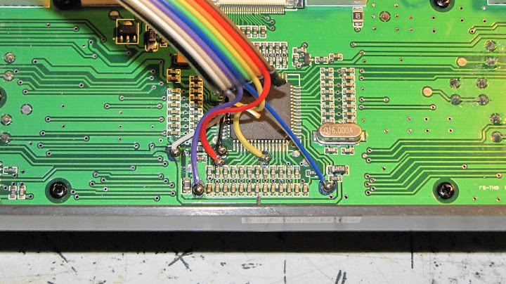
  • In new model 9x's (the ones with a single antenna), there is a circuitry problem that blocks the trainer port.
  • The simple way to fix this problem is to pop the module out.  The antenna connection is soldered to the main board, so be a little bit careful.  You have 2-3 cm of loose antenna wire.
  • With the module disconnected, the trainer port is active.  I think it's ok to operate in this mode, just tape the module so it doesn't fall out and break the antenna wire.
  • Another solution, but more work, is to solder a resistor into the circuit.  I have not tried this yet, but have my notes on this page.
Teacher Radio
  • Turn on trainer channels [menu / func setting / trainer].
  • You can turn on all controls or just some.  It might be useful for teacher to keep control of the throttle, for example.
  • The settings are confusing.  I will probably make a video, but I think you want to set Off/On mode. When in that menu, pull the trainer switch and you should see the mode switch.
  • In most radios, you pull the trainer switch to allow student control, and let go of trainer switch for teacher to control.
  • Turnigy 9x is opposite!  Must hold trainer switch for teacher to control.  Use this method for mechanical reverse.
Simple Summary
  • Eject the module from student radio.  Tape it down so it doesn't break antenna wire.
  • Make sure "Reverse" has same settings on both radios. [menu/func setting/reverse].
  • Set trainer mode on teacher radio.
  • Attach mono cable to both radios.
  • Test all controls to see if reverse is correct on both radios.
  • Fly!

Wednesday, September 21, 2011

Using a LiPo in a Turnigy 9X radio

Here's how I replaced the battery pack on my Turnigy 9X radio.  Andreas did it first... I just copied what he did.

It's pretty simple: cut the connector off of the original battery pack (the one that holds 8 AA cells) and solder on your favorite connector to the just-cut wire.  I picked JST because it was small and didn't take up much room in the case.
I used an old 3S 1800 mAh battery that I wasn't using for anything else.  A 2S battery will also work.  RC Model reviews has a popular article on swapping out the battery.  It's a comprehensive solution, and involves resoldering the motherboard.

The method presented here is a lot simpler.  You don't have to touch the main board, but you lose the low voltage beeper.  That means it's possible to discharge the LiPo battery below 3V/cell.  You just have to be careful at the start of the day to have the battery charged to 10V or more.
The discharge rate is about 0.1V/hour, so if you're charged to 10V or above, you will probably be OK.

Be careful when soldering your connector not to reverse the polarity.  There's no polarity protection on the motherboard, so if you get it wrong you'll fry your unit!

That being said, it's working well for me.


Update: the old battery I was using started having problems with one of the cells.  I didn't have another conveniently sized LiPo, so I replaced it with a LiFe battery from HobbyKing.  Notes on that are here:

http://eastbay-rc.blogspot.com/2011/10/life-battery-in-turnigy-9x.html

Update: Javio left me a great comment on diydrones that goes into detail on how the LM7805 voltage regulator works:


There is a little confusion about the best 2S vs 3S better battery for the 9X. If conceptually it is true that a bigger dropout voltage between input and output leads in a bigger heat dissipation, the 7805 regulator has been designed to give the best performances with a differential voltage between input and output of about 5 to 10V. With the 7,5V (from 6V depending on the model) minimum input required voltage (2,5V of differential dropout voltage between input and output for 7805) the output peak current can not be achieved (the regulator can´t work at full dynamic range). In fact the factory testings of the LM7805 are done with a typical input voltage of 10V. Following this lines, and assuming that the input regulator is a 78xx, a 3S Lipo battery should be a better candidate than 2S to power the turnigy 9X. You can check the Peak Output Current Vs differential input-output voltage characteristic in the figure of page 21 of the attached datasheet or the Droupout voltage characteristic googleing "7805".
This explanation does not means that a 2S is a bad option, but in this case the regulator won´t work at full dynamic range of its output current. By the way, looking the datasheets a dropout of 5 to 7V between input and output (corresponding to an input voltage between 10 and 12V) doesn´t lead in a significative amount of heat increase.
Cheers from Spain.
Javio


Thursday, August 25, 2011

Wireless Trainer Port

Saw this linked from RCGroups, but couldn't figure out who did it or where it's written up.

Basic Idea:

  • student's Tx is bound to the Rx
  • Rx has trainer cable wired to battery port
  • PPM signals feed into the trainer port from the receiver
  • For simulator, can power from USB

Monday, July 18, 2011

Resistor Mod, fix for Turnigy 9x trainer port

Many people have written this up, this page shows two different ways to fix, with nice photos.

Update: I modded my unit so the radio is purely module based;  This lets me just pop out the module, so I've lost interest in doing this.

Saturday, May 7, 2011

Ardupilot Mega 2.1, Happy Killmore Ground Control

Getting the hang of this... here's the latest APM.


Still to to on Turnigy 9x:
  • figure out failsafe
  • figure out mixing, so 3-way switch can control