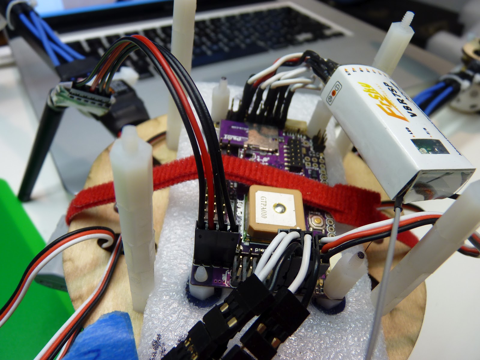
So Andreas saw the Flitetest video on the F22 and got the mood to cut out one for himself. He called me up and asked if I had any 9mm EPP foam. I did, and all the electronics and hardware necessary, courtesy of my prior thought to try to get the scouts to build some planes. I was thrilled to be able to put these to use, and Andreas said he would cut out an extra one for me. Here's the pieces cut out.
And now glued up. Very nice! That's an 8x4 prop on a 1500 kV blue wonder motor. 18A ESC, 500 mAH 3S batteries, 9g servos.
View from the bottom. Those are 3mm carbon tubes running laterally. Bamboo skewers on the leading edge and for the push rods.
Here's mine, ready to glue up. Using Beacon Foam-Tec, including the hinges.
And completed! Elevon flight controls following the new East Bay Elevon standard, coming up in another post.
Flight test upcoming! It will be fun to be flying something that only has two CPUs on board.
Here's the thread and plans by original designer dekan.
Saturday, May 26, 2012
Friday, May 25, 2012
Building ArduPilot Mega on Mac
Here how I set up Arduino to compile ArduPlane and ArduCopter on the Mac.
Install Arduino
Connect your APM to the computer via USB
Run Arduino and configure the environment
Compile (Verify) the ArduPlane software
Upload to APM
Working on the Arducopter software
Working with git
Install Arduino
- Download the latest 1.x release from http://arduino.cc/en/Main/Software.
- Unzip and install into the Applications folder.
- Get the newest copy of Arduplane from the Ardupilot repository. I grabbed version 2.34.
- My home directory is /Users/mh, and my working directory is /Users/mh/apm
- Change to the working directory and unzip ArduPlane-2.34.zip.
- You should see these directories. There's some others that you can ignore.
/Users/mh/apm/ArduPlane-2.34
/Users/mh/apm/ArduPlane-2.34/ArduPlane
/Users/mh/apm/ArduPlane-2.34/libraries
Connect your APM to the computer via USB
- IF YOUR APM IS ON AN AIRCRAFT, DISCONNECT THE AIRCRAFT BATTERIES OR REMOVE THE PROPS!
- No kidding, the props can spin up unexpectedly and send you to the hospital for stitches!
Run Arduino and configure the environment
- Run the Arduino program. Restart it if it was already running so that it can see the APM USB connection.
- Set the CPU type: Tools / Board / Arduino Mega 2560 (AtMega 1280 for APM1)
- Set the APM serial port: Tools / Serial Port / /dev/tty.*usb* The name will vary, look for tty and usb.
- Set the sketchbook location: Arduino / Preferences... / Sketchbook Location
- Set it to the unzipped directory; In my case: /Users/mh/apm/ArduPlane-2.34
- Quit Arduino and Restart.
- Double check that the above three settings are still good.
Compile (Verify) the ArduPlane software
- File / Open... and navigate to /Users/mh/apm/ArduPlane-2.34/ArduPlane
- Open ArduPlane.pde. This will give you a window with several files opened in tabs.
- Click the Verify button.
- After a while, you should get a message like "Binary sketch size: 157,232 bytes (of a 258,048 byte maximum)"
Upload to APM
- Click the Upload button.
- You should see the APM serial light blink furiously
- You should get the message "*******"
Working on the Arducopter software
- note: There's some unorthogonality with the downloaded Arducopter zip file. There's no intermediate directory with a version number.
- Grab the newest copy of ArduCopter from the ArduCopter repository. I grabbed version 2.5.5.
- Unzip ArduCopter-2.5.5.zip in some scratch directory. This will give you two directories, Arducopter and libraries. libraries is identical to the ArduPlane version, so you can ignore it.
- Delete the directory ArduPlane-2.34/ArduCopter
- Copy ArduCopter to ArduPlane-2.34.
- You should see the directory ArduPlane-2.34/ArduCopter.
- In Arduino, open the file ArduPlane-2.34/ArduCopter/ArduCopter.pde.
- Compile and Upload as described above!
Working with git
- The Arduplane projects are hosted on Google Code. Get a Google account if you don't have one.
- Instructions for checking out are on the ArduPilot source page.
- You don't need to grab ArduCopter separately. It will be in the ArduCopter directory as described above. If you do grab it, it will have a single file pointing you to the ArduPlane repository.
Using command line tools
- There are notes in README.txt
- tl;dr: cd ArduPlane; make configure; edit ../config.mk; make; make upload
- I had to edit the following entry in libraries/AP_Common/Arduino.mk to add the -C parameter.
upload: $(SKETCHHEX) $(AVRDUDE) -c $(UPLOAD_PROTOCOL) -p $(MCU) -P $(PORT) -b$(UPLOAD_SPEED) -U flash:w:$(SKETCHHEX):i -C /Applications/Arduino.app/Contents/Resources/Java/hardware/tools/avr/etc/avrdude.conf
Thursday, May 24, 2012
Zephyr II and ArduPilot Layout
Here's a few notes by Andreas on laying out a Zii with an Ardupilot Mega.
This is his first Zii. One 5000 mAh 3S or one 3000 mAh 4S battery is placed sideways at the nose.
In his second Zii, he started with a plywood battery box. He cut this himself; it's sized to hold two 4000 mAh 3S Turnigy Nano batteries.
.JPG)
To keep the radio components separated, he:
This is his first Zii. One 5000 mAh 3S or one 3000 mAh 4S battery is placed sideways at the nose.
To keep the radio components separated, he:
- moved the video transmitter all the way to the winglet
- put the RC receiver is in the center of the wing on the opposite side
- put 3DR radio close to the APM in the main compartment
He mounted the ESC above the APM.
Tuesday, May 22, 2012
Aerial view of KGO interview
We had a nice interview with KGO San Francisco today. Flew the quad and Zii in some pretty stiff winds -- there were whitecaps on the Bay when I was leaving.
For one of the segments I put the quad in position hold behind me, and answered the interview questions while holding the radio. I was impressed with the position stability given the high wind.
Here's a snippet of the interview, drone's-eye-view:
Sunday, May 20, 2012
Zeiss Cinemizer goggles
Here's the upcoming OLED Cinemizer goggles. Close to $1,000, definitely nice looking... but too bad, they only go to +5 diopters. I shall use them as style inspiration for my homemade set!
Wednesday, May 16, 2012
Some East Bay Magnetic Declination Numbers
Because you never know when you'll need them! From magnetic-declination.com.
Location Latitude Longitude Declination
BERKELEY 37° 52' 18" N 122° 16' 18" W 14° 7' EAST
PIEDMONT 37° 49' 28" N 122° 13' 50" W 14° 6' EAST
CONCORD 37° 58' 41" N 122° 1' 48" W 14° 6' EAST
Location Latitude Longitude Declination
BERKELEY 37° 52' 18" N 122° 16' 18" W 14° 7' EAST
PIEDMONT 37° 49' 28" N 122° 13' 50" W 14° 6' EAST
CONCORD 37° 58' 41" N 122° 1' 48" W 14° 6' EAST
Tuesday, May 15, 2012
Is it foggy in the Bay?
Is it foggy in the East Bay? Here's a fog forecast page:
http://www.sfgate.com/weather/fog/fogtopclose.shtml
And some webcams of the bay. The first one shows the Berkeley Marina directly:
http://sv.berkeley.edu/view/index.html
http://www.mapwest.com/bridgecam_main.html
http://cams.exploratorium.edu:8010/
http://rntl.net/sausalitocam.htm
http://webmarin.com/http://webmarin.com/
http://www.sfgate.com/weather/fog/fogtopclose.shtml
And some webcams of the bay. The first one shows the Berkeley Marina directly:
http://sv.berkeley.edu/view/index.html
http://www.mapwest.com/bridgecam_main.html
http://cams.exploratorium.edu:8010/
http://rntl.net/sausalitocam.htm
http://webmarin.com/http://webmarin.com/
Monday, May 14, 2012
Andreas' Heavy Lift Quad Tests
Missed posting this a couple of weeks ago... Two lift tests by Andreas, 4 lbs and 8 lbs. Pretty impressive!
Zii Battery Tray by Team Blacksheep
Thursday, May 10, 2012
Thursday Miscellanea
When I started this blog, I made it a point that it would be mostly my own words. If it weren't something I was actually doing myself, I would write at least a little about whatever it was I was posting a link to.
As a result, I often have a half-dozen or more browser windows open to various interesting things, waiting to be written about. I think I'm going to start a weekly post to collect these things. I'll try doing every Thursday evening, based on the logic that I've got a few things open now and it's Thursday evening.
- KapteinKuk discusses his firmware to convert a Turnigy ESC to a brushless controller. Source code included!
- APM quad test harness.
- Why to ream a prop from the "insert side".
- ReadyMadeRC has some FPV stuff, including a tiny camera.
- Covering a foamy wing.
- Drill press on sale at Harbor Freight.
Monday, May 7, 2012
Imperial Screw Sizing
So I was trying to make a mount for my new Sony cam which has pre-drilled M2 (2mm) mounting holes. Just the wrong size for a 4-40 standoff!!!
Here's the formula for Unified threads -- those are the ones with a #1 - #10 at the front.
major thread diameter = 0.060'' + (0.013" * N)
The second number (i.e. 40) is the number of threads/inch.
So a #4-40 has a major diameter of 0.112", or 2.8448mm.
Here's the formula for Unified threads -- those are the ones with a #1 - #10 at the front.
major thread diameter = 0.060'' + (0.013" * N)
The second number (i.e. 40) is the number of threads/inch.
So a #4-40 has a major diameter of 0.112", or 2.8448mm.
Build-a-Quad Kit
I received a couple of emails asking about building a quad, and how much it would cost in parts to do it yourself rather than buying a ready-to-fly model.
Here's a HobbyKing based shopping list. I think it's pretty feasible, a lot easier than building a plane since there's no moving parts. You will need some basic soldering to put connectors on the speed controller.
Executive summary: quad parts, about $230 including shipping. radio and charger, about $100.
Frame and Power Distribution. There's a lot of latitude in the frame. You can make one out of old boards and plywood for almost free. This is a popular frame and good for a first unit. The power distribution board lets you easily hook up the speed controllers to the battery.
$20 Hobbyking X550 Glass Fiber Quadcopter Frame 550mm
$ 4 Hobby King Quadcopter Power Distribution Board
Power System. This includes the motor and motor controller. You will need four of each. The NTM motors need an accessory kit for mounting (thanks to Andreas for catching this!)
$40 (four) HobbyKing 20A BlueSeries Brushless Speed Controller
$64 (four) NTM Prop Drive 28-26 1350KV / 310W
$ 8 (four) NTM Prop Drive 35 Series Accessory Pack
Control Board. There are lots of options for control boards. This is one of the simplest and cheapest. It's good, but doesn't have stabilized mode. It's what I started with, except when I bought mine it was $150! See below for other options. You'll need the programming cable if you ever want to update the programming.
$20 HobbyKing Multi-Rotor Control Board V3.0 (Atmega328 PA)
$ 5 USBasp AVR Programming Device for ATMEL proccessors
Batteries. If you're in the US, it will probably be cheaper (counting shipping) to order separately from the US warehouse. You will probably want two to begin with.
$19 Turnigy nano-tech 2200mah 3S 35~70C Lipo Pack
Turnigy nano-tech 2200mah 3S 35~70C Lipo Pack (USA Warehouse)
Props. You need two each "normal" props and two each "reverse" props. It doesn't hurt to get an extra bag of each, as they are the thing which you will break most frequently as you learn to fly.
Shipping. I'm estimating about $30-$40 or so for all of this.
Other items you will need. Once you have a battery charger and radio you are good to go on the ground side.
Battery Charger. These come in all sizes and price ranges. These are three units that I have personal experience with.
$12 Turnigy 2S 3S Balance Charger. Direct 110/240v Input
Transmitter/Receiver. Tons to choose from. The 9x is a nice low-price unit. It comes with a receiver; extras are about $10 each. You want a "mode 2" which means the throttle is on the left stick. These are frequently on backorder. The Internet believes there's a new model coming.
$55 Turnigy 9X 9Ch Transmitter w/ Module & 8ch Receiver
Camera Mount. This one is designed for the X550 above.
$13 Hobbyking X550 Glass Fiber Tilt Camera Mount
Here's a HobbyKing based shopping list. I think it's pretty feasible, a lot easier than building a plane since there's no moving parts. You will need some basic soldering to put connectors on the speed controller.
Executive summary: quad parts, about $230 including shipping. radio and charger, about $100.
Frame and Power Distribution. There's a lot of latitude in the frame. You can make one out of old boards and plywood for almost free. This is a popular frame and good for a first unit. The power distribution board lets you easily hook up the speed controllers to the battery.
$20 Hobbyking X550 Glass Fiber Quadcopter Frame 550mm
$ 4 Hobby King Quadcopter Power Distribution Board
$40 (four) HobbyKing 20A BlueSeries Brushless Speed Controller
$64 (four) NTM Prop Drive 28-26 1350KV / 310W
$ 8 (four) NTM Prop Drive 35 Series Accessory Pack
Control Board. There are lots of options for control boards. This is one of the simplest and cheapest. It's good, but doesn't have stabilized mode. It's what I started with, except when I bought mine it was $150! See below for other options. You'll need the programming cable if you ever want to update the programming.
$20 HobbyKing Multi-Rotor Control Board V3.0 (Atmega328 PA)
$ 5 USBasp AVR Programming Device for ATMEL proccessors
Batteries. If you're in the US, it will probably be cheaper (counting shipping) to order separately from the US warehouse. You will probably want two to begin with.
$19 Turnigy nano-tech 2200mah 3S 35~70C Lipo Pack
Turnigy nano-tech 2200mah 3S 35~70C Lipo Pack (USA Warehouse)
Connectors. If you get the motors and power distribution board above, you will need two packages of this connector for your speed controllers.
Shipping. I'm estimating about $30-$40 or so for all of this.
Other items you will need. Once you have a battery charger and radio you are good to go on the ground side.
Battery Charger. These come in all sizes and price ranges. These are three units that I have personal experience with.
$12 Turnigy 2S 3S Balance Charger. Direct 110/240v Input
At the low end... plugs into wall, works well but wil
take about 4 hours to recharge the batteries above.
Needs to be plugged into your car or an external
12V power converter. Will charge in about 1.5 hours.
Needs to be plugged into your car or an external
12V power converter. Will charge in about 30 minutes
Transmitter/Receiver. Tons to choose from. The 9x is a nice low-price unit. It comes with a receiver; extras are about $10 each. You want a "mode 2" which means the throttle is on the left stick. These are frequently on backorder. The Internet believes there's a new model coming.
$55 Turnigy 9X 9Ch Transmitter w/ Module & 8ch Receiver
$13 Hobbyking X550 Glass Fiber Tilt Camera Mount
Sunday, May 6, 2012
Awesome Hex by Andreas!
Andreas made a Hex today! He started looking at it a couple of days ago after doing some weight testing on his Quad. He's posted some notes over at diydrones. Total frame cost, about $10! He printed a cutting guide on paper and glued it to the plates for a cutting and fitting template. Here's the arms glued into the two plates.
Fitting the power distribution. Note that he's bolted the arms as well. It uses two batteries, each powering three motors in a triangular arrangement -- hopefully a power system failure will allow the three remaining motors to get the unit to the ground without a smashup.
And later that evening, it was ready to fly. This is why it's so much fun hanging around this guy!!
Fitting the power distribution. Note that he's bolted the arms as well. It uses two batteries, each powering three motors in a triangular arrangement -- hopefully a power system failure will allow the three remaining motors to get the unit to the ground without a smashup.
And later that evening, it was ready to fly. This is why it's so much fun hanging around this guy!!
Tuesday, May 1, 2012
RCTimer ESC's easily flashable
There's a nice RCGroups post showing that the RCTimer ESCs are easily flashable, withe the pads conveniently aligned on the edge of the unit. They use tgy.hex.
Humor Break
I think a lot of readers will identify with this!
"One day, son, all of these perfectly good A.C. adapters, which have long outlived teh products they were originally designed for, will be yours."
Not sure of the source, somebody sent it to me...
"One day, son, all of these perfectly good A.C. adapters, which have long outlived teh products they were originally designed for, will be yours."
Not sure of the source, somebody sent it to me...
Miles of Free Servo Wire!
Here's a thread I started on RCGroups, verifying that ethernet cable was a good source of 24 gauge wire. It is! There are 8 wires (4 twisted pairs) in each cable. Make sure the wires are stranded and not solid, and you've got all the wiring you need, albeit in rather pastel coloration.
For me it's OK, I'm using it to make some custom receiver/APM connectors. I'll make pin 1 be the odd color on each side.
I use this great servo crimp kit from Hansen Hobbies.
The plastic part is sold as:
Harwin M20-1061200 12 PIN SIL HOUSING
The "12" in the part number goes from 01 to 12, and indicates the number of slots. I found the best value is to buy the 12 slot units and trim them down to size. They cut easily with a box cutter.
For me it's OK, I'm using it to make some custom receiver/APM connectors. I'll make pin 1 be the odd color on each side.
I use this great servo crimp kit from Hansen Hobbies.
The plastic part is sold as:
Harwin M20-1061200 12 PIN SIL HOUSING
The "12" in the part number goes from 01 to 12, and indicates the number of slots. I found the best value is to buy the 12 slot units and trim them down to size. They cut easily with a box cutter.
LiFe battery in a 4x2x2 battery compartment
Somebody on RCGroups was asking about how LiFe batteries fit into receivers with a 4x2x2 battery compartment, similar to what's on a Turnigy 9x. Here's some pictures of how it fits (summary: just right!). There's no stress on the battery compartment cover when snapping it on, and just enough room for the wires. Use the power connector that looks like a servo connector.
HobbyKing 1500mAH LiFe 3S 9.9v Transmitter pack
It fits nicely in this configuration, but the 9x power connector is blocked. This may or may not affect you depending on your receiver's connector configuration.
HobbyKing 1500mAH LiFe 3S 9.9v Transmitter pack
It fits nicely in this configuration, but the 9x power connector is blocked. This may or may not affect you depending on your receiver's connector configuration.
Sunday, April 29, 2012
Some Quad Gimbal Links
For future investigation...
Photohigher AV130 Tilt-Roll Gymbal
700 pounds
Photohigher AV200 Pro Camera Gimbal
$950
All CarbonCore mounts
Naza Flamegear
all mounts
AG550-NX Landing Gear+2 Axis Camera Gimbal
Cinestar 2 Axis Gimbal
MC6500PRO 2 axis camera mount
$189
MC 6500 V3 dual axis cam mount
another review
DS01 Gimbal for DSLR Camera
$299
Photohigher AV130 Tilt-Roll Gymbal
700 pounds
Photohigher AV200 Pro Camera Gimbal
$950
All CarbonCore mounts
Naza Flamegear
all mounts
AG550-NX Landing Gear+2 Axis Camera Gimbal
Cinestar 2 Axis Gimbal
MC6500PRO 2 axis camera mount
$189
MC 6500 V3 dual axis cam mount
another review
DS01 Gimbal for DSLR Camera
$299
Strain Relief Carrier for 3DR Ground Module
Thanks to a comment by Andreas M. Antonopoulos about the fragility of the USB connector, I made a small ground module case that seems to provide a lot of strain relief.
It's pretty simple -- I cut it out of thin cardboard, scoring the cardboard so it would fold neatly around the unit and the USB connector. The scorings are 10mm, 20mm, 10mm apart. I cut out a window to see the LEDs on the board.
Here it is all taped up. The tightest part is wrapped around the USB connector. Tomorrow I'll leave it plugged in for a while and make sure it's not getting too hot. If it is, I'll try expanding the hole, or even just trimming it off and only keeping the strain relief on the USB part of the board. (update: no apparent heat buildup at all.)
I taped the side with strapping tape to keep the rectangular shape and put a piece of velcro on it. If I had a 3D printer or a laser cutter I would probably go crazy making stuff like this, but the cardboard seems to work nicely.
I didn't want the cable catching on things, so I ordered a 1 foot USB extension cable from Amazon and used that cable instead of the one that shipped with the unit. I pulled the cable around the back just enough so that it removed the slack, but not so much that it caused any strain for the USB port. A right-angle USB cable would be perfect, but I don't think I've seen one.
Here's the view from the back. I'll measure the signal strength later and make sure I'm not causing any interference.
It's pretty simple -- I cut it out of thin cardboard, scoring the cardboard so it would fold neatly around the unit and the USB connector. The scorings are 10mm, 20mm, 10mm apart. I cut out a window to see the LEDs on the board.
Here it is all taped up. The tightest part is wrapped around the USB connector. Tomorrow I'll leave it plugged in for a while and make sure it's not getting too hot. If it is, I'll try expanding the hole, or even just trimming it off and only keeping the strain relief on the USB part of the board. (update: no apparent heat buildup at all.)
I taped the side with strapping tape to keep the rectangular shape and put a piece of velcro on it. If I had a 3D printer or a laser cutter I would probably go crazy making stuff like this, but the cardboard seems to work nicely.
I didn't want the cable catching on things, so I ordered a 1 foot USB extension cable from Amazon and used that cable instead of the one that shipped with the unit. I pulled the cable around the back just enough so that it removed the slack, but not so much that it caused any strain for the USB port. A right-angle USB cable would be perfect, but I don't think I've seen one.
Here's the view from the back. I'll measure the signal strength later and make sure I'm not causing any interference.
Saturday, April 28, 2012
RangeVideo 1.3GHz Video TX-RX
Finally got my RangeVideo 1.3GHz electronics figured out and assembled... hooray! Here's the camera, Tx, Rx, and video monitor. I'm using a Sony DVD player that a coworker was getting rid of as the monitor. It's nice coz it's self-contained with its own battery. It has video and audio input. Just one problem, which I'll note below.
Here's the Rx side. I made a power cord so it can run off a 3S Lipo. I'm planning on using the cheap 2.2mAh Turnigys, since the current draw is minimal. The Rx is set to channel 9, 1280GHz. That's the only channel legal in the U.S. You need a Ham technical license to use it. The channel indicator is almost totally black... hard to see even with the lights off.
Notice the taped-over yellow RCA jack? I lost hours trying to troubleshoot the setup, only to find out that my replacement cable for the DVD player was wired backwards -- the audio comes through the yellow jack and the video through the black one. Troubleshooting everything was a pain, since I was integrating 4 new pieces that I had never used before. Lesson learned: check the cables first!
Here's the Tx. It's also running off a 3S. The unit gets surprisingly hot, will need to find a way to keep it cool. The camera is a Sony. I had to make a cable for it.
Here's the cable I made. The board connector is a 1.5mm pitch Molex Picoblade. Believe me, it wasn't easy to find that out! The camera vendor sold double-ended pigtails. Of course they didn't mention that anywhere, so it added about a month to research this and have the cable sent. I snipped it in half and put a servo-style connector so that it would fit the RangeVideo cable harness.
I took the chance to measure the power consumption. Subtracting the base usage of the watt meter (.3A, 4.0W at 12V), I measured the following numbers (all at 12V, which is what both the Tx and Rx use:
Rx: 0.3A, 3.7V
Tx + cam: 0.3A, 3.0V
cam (no Tx): 0.1A, .5W
Here's another shot of the camera cable. Hansen Hobbies sells the Pico connector but currently doesn't sell the crimping tool. I ordered some connectors anyways... I'll see if there's any other way to crimp them.
Here's my power cable. I snipped off the 2.1MM power connector from an old wall wart and soldered it onto an XT60 connector. If you toss any old wall warts be sure and save this piece! Be careful to get your polarity right as well.
Here's the Rx side. I made a power cord so it can run off a 3S Lipo. I'm planning on using the cheap 2.2mAh Turnigys, since the current draw is minimal. The Rx is set to channel 9, 1280GHz. That's the only channel legal in the U.S. You need a Ham technical license to use it. The channel indicator is almost totally black... hard to see even with the lights off.
Notice the taped-over yellow RCA jack? I lost hours trying to troubleshoot the setup, only to find out that my replacement cable for the DVD player was wired backwards -- the audio comes through the yellow jack and the video through the black one. Troubleshooting everything was a pain, since I was integrating 4 new pieces that I had never used before. Lesson learned: check the cables first!
Here's the Tx. It's also running off a 3S. The unit gets surprisingly hot, will need to find a way to keep it cool. The camera is a Sony. I had to make a cable for it.
Here's the cable I made. The board connector is a 1.5mm pitch Molex Picoblade. Believe me, it wasn't easy to find that out! The camera vendor sold double-ended pigtails. Of course they didn't mention that anywhere, so it added about a month to research this and have the cable sent. I snipped it in half and put a servo-style connector so that it would fit the RangeVideo cable harness.
I took the chance to measure the power consumption. Subtracting the base usage of the watt meter (.3A, 4.0W at 12V), I measured the following numbers (all at 12V, which is what both the Tx and Rx use:
Rx: 0.3A, 3.7V
Tx + cam: 0.3A, 3.0V
cam (no Tx): 0.1A, .5W
Here's another shot of the camera cable. Hansen Hobbies sells the Pico connector but currently doesn't sell the crimping tool. I ordered some connectors anyways... I'll see if there's any other way to crimp them.
Here's my power cable. I snipped off the 2.1MM power connector from an old wall wart and soldered it onto an XT60 connector. If you toss any old wall warts be sure and save this piece! Be careful to get your polarity right as well.
Saturday, April 21, 2012
Review: Open Source Cardboard Boxes
Thanks to 3DRobotics, 2012 is shaping up to be a banner year for Open Source Hardware cardboard boxes. From the top:
- DSO Nano box from Seeed Studio. Perhaps the most trancendentally cool of all the boxes.
- 3D Robotics. Elegant and understated, this black box will be immediately identifiable in the hands of a delivery man.
- Sparkfun Inventor's Kit. Possibly the first colorful open source box, it shows the innovative spirit that has inspired so many people in the open source hardware community.
- Solarbotics. Keeping in line with their straightforward engineering excellence, they're still using the sturdy but artistically uninspiring official Canada Post box.
- As a reference point, the final container is the incredibly well reviewed box from our uncle in Hong Kong who regularly sends us boxes of gifts with a negligable cash value. Cheap, somewhat shabby, taped to the hilt, it is the reference point for utilitarian delivery of goods from one continent to another.
Overall, I think you'll agree that the Open Hardware people are excelling not only in innovative designs, but their creativity and craftsmanship is evident in their boxes as well!
Setting the Network Address on the 3DR air radio
As I was mentioning in the previous post, everything went smoothly and I'm currently in love with my new 3DR radio. Thanks Tridge, once again I'm in your debt!
The only snag I hit was when I was changing the network ID away from the default.
I followed the directions to do so, and everything went great up until I saved the settings. I got a popup indicating that the air unit had an error saving the settings. Like Han Solo, I had a bad feeling... I might now have the two units set to two different network ids: the ground radio updated to 26, and the air radio still on 25.
That's indeed what seemed to be the case: reloading the settings worked fine for the ground radio, but the air radio couldn't be contacted.
At this stage I could have tried resetting the ground radio back to network 25. That would have been the easiest thing to try, and would have worked fine to get the radios talking.
But I had noticed that the air radio pins were a standard FTDI connection, so I had another thought. Perhaps I could connect the air radio to the computer via an FTDI adapter, and set it to network 26 that way. I have the industry standard sparkfun FTDI adapter, so I gave it a try.
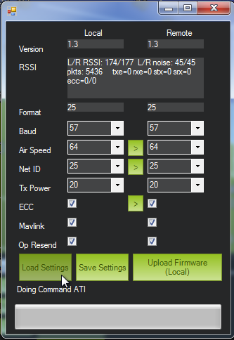
And hooray, it worked. Hook it up, start up the APM software, select the proper COM device and set the baud rate to 57600. DO NOT try and connect. Select Configuration/3DR Radio to bring up the configuration screen. "Load Settings" worked as expected, and showed that I was correct in thinking that the network ID was still 25. I changed to to 26, saved, put the air unit back on the APM, and reattached the ground unit.
I ran the APM Planner again, and everything worked like a charm. I could read (and set!) the air radio settings, and connecting the APM in the APM planner worked as expected.
(toc: 3DR Radio)
The only snag I hit was when I was changing the network ID away from the default.
I followed the directions to do so, and everything went great up until I saved the settings. I got a popup indicating that the air unit had an error saving the settings. Like Han Solo, I had a bad feeling... I might now have the two units set to two different network ids: the ground radio updated to 26, and the air radio still on 25.
That's indeed what seemed to be the case: reloading the settings worked fine for the ground radio, but the air radio couldn't be contacted.At this stage I could have tried resetting the ground radio back to network 25. That would have been the easiest thing to try, and would have worked fine to get the radios talking.
And hooray, it worked. Hook it up, start up the APM software, select the proper COM device and set the baud rate to 57600. DO NOT try and connect. Select Configuration/3DR Radio to bring up the configuration screen. "Load Settings" worked as expected, and showed that I was correct in thinking that the network ID was still 25. I changed to to 26, saved, put the air unit back on the APM, and reattached the ground unit.
I ran the APM Planner again, and everything worked like a charm. I could read (and set!) the air radio settings, and connecting the APM in the APM planner worked as expected.
(toc: 3DR Radio)
Review: 3DR 900MHz Radio
The much-anticipated 3DR radio arrived yesterday, in the stylish new 3DR black box. Hooray! After having so much xbee grief, I had high hopes that this would solve all my telemetry-related problems.
TLDR: it's great!
As advertised, the kit comes with a ground radio, an air radio, two antennas, cables for each, and a header for the air radio. As a nice bonus, they included enough 1-1/4'' shrink tube to cover both radios. Nice!
Here's what the radio units look like. The ground unit plugs directly into a USB. Both Mac and Windows 7 recognized it and downloaded the proper driver. The included ground cable is a standard USB extension cable. (Use the cable, and don't plug the ground unit directly into a USB port. There's no other attachment to the board other than the soldered connections, so the USB connector will break off if there's any stress applied while in the computer's USB port. Thanks to Andreas Antonopoulos for this tip!)
As you can see here, the air unit doesn't have the headers soldered on.
The approximate weight of the air unit is 17.4 grams, not counting solder or shrink tube. It's possible to replace the antenna with a lighter quarter-wave wire antenna. Tridge mentioned that he did some of his initial testing with such a setup.
Stick a label onto your antenna before you get it mixed up with a 2.4GHz or other sized antenna. They look pretty similar but won't work.
Here's how to attach the air unit cable. Use the end of the cable that has the 5-pin plug.The RTS pin is left bare, and the wire gap is closest to GND. If you've got the red wire on 5V you're good -- there's only one orientation where that works.
Here's the air unit shrink wrapped and with cable attached.
Here's the radio pins on the APM2. It's located at the rear of the board. There are four pins, and you use the end of the cable that has the four-pin connector.
Looking forward (as in this picture), the red power wire is towards the left.
Once the air unit is hooked up, power on the APM, attach the ground unit to your computer (via USB), run the APM planner, and press control-A. Be sure to be in disconnected mode. You will get the 3DR radio configuration screen. Press "Load Settings" and you should get the settings for both the ground and air radios. Exit this screen, and you should be able to connect as normal. The configuration was read immediately (no "timeout in ..." messages!!) It took about 5 seconds from connect time for the APM Planner to start responding.
Once you've verified it's working, you will want to change the network ID if you're planning on flying near anybody else using a 3DR radio.
Summary: overall I'm very happy. I spend about an hour setting things up (including taking pics and notes), and it's working smoothly.
Viewing Radio Stats
Michael Oborne points out: 'in the planner under "Status" and "tuning" you can see all the values tridge included in his graph live.'
What to do if your network binding goes awry
Of course, this would not be a certified Mark Harrison Radio Experience (tm) if at least one thing did not go wrong. In this case, changing the network ID failed on the air radio, so I was stuck with a ground radio with an ID of 26 and an air ID of 25. Fortunately this was not too difficult to clear up; I'll cover that in the next post. (update: here.)
TLDR: it's great!
As advertised, the kit comes with a ground radio, an air radio, two antennas, cables for each, and a header for the air radio. As a nice bonus, they included enough 1-1/4'' shrink tube to cover both radios. Nice!
Here's what the radio units look like. The ground unit plugs directly into a USB. Both Mac and Windows 7 recognized it and downloaded the proper driver. The included ground cable is a standard USB extension cable. (Use the cable, and don't plug the ground unit directly into a USB port. There's no other attachment to the board other than the soldered connections, so the USB connector will break off if there's any stress applied while in the computer's USB port. Thanks to Andreas Antonopoulos for this tip!)
As you can see here, the air unit doesn't have the headers soldered on.
The approximate weight of the air unit is 17.4 grams, not counting solder or shrink tube. It's possible to replace the antenna with a lighter quarter-wave wire antenna. Tridge mentioned that he did some of his initial testing with such a setup.
Stick a label onto your antenna before you get it mixed up with a 2.4GHz or other sized antenna. They look pretty similar but won't work.
Here's how to attach the air unit cable. Use the end of the cable that has the 5-pin plug.The RTS pin is left bare, and the wire gap is closest to GND. If you've got the red wire on 5V you're good -- there's only one orientation where that works.
Here's the air unit shrink wrapped and with cable attached.
Here's the radio pins on the APM2. It's located at the rear of the board. There are four pins, and you use the end of the cable that has the four-pin connector.
Looking forward (as in this picture), the red power wire is towards the left.
Once you've verified it's working, you will want to change the network ID if you're planning on flying near anybody else using a 3DR radio.
Summary: overall I'm very happy. I spend about an hour setting things up (including taking pics and notes), and it's working smoothly.
Viewing Radio Stats
Michael Oborne points out: 'in the planner under "Status" and "tuning" you can see all the values tridge included in his graph live.'
What to do if your network binding goes awry
Of course, this would not be a certified Mark Harrison Radio Experience (tm) if at least one thing did not go wrong. In this case, changing the network ID failed on the air radio, so I was stuck with a ground radio with an ID of 26 and an air ID of 25. Fortunately this was not too difficult to clear up; I'll cover that in the next post. (update: here.)
Subscribe to:
Posts (Atom)


.jpg)