Pages

Friday, May 27, 2011

Elevon / V-Tail Mixing Calculations

update: moved this into its own post.  original elevon description here.
Calculating Elevon Motion

There are two calculations, one for each elevon:

        a = x/2 - y/2
        b = x/2 + y/2

where
  •  a = left elevon deflection,
  •  b = right elevon deflection,
  •  x = aileron position (-1 = far left, 0 = centered, 1 = far right),
  •  y = elevator position (likewise, -1 .. 1)

Deriving the Elevon Calculation

I couldn't find the above formula anywhere on the web, probably because it's so obvious to everybody but me.  Here's how I figured it out.  Real mathematicians would do it much easier I'm sure!

First, look at the inputs and outputs.  The above video shows the endpoints and midpoints of the two axes.

which gives us this table for the values of A and B:

    a,b = f(x,y):
                 x=-1.0       x=0.0         x=1.0
        y=1.0    -1.0, 0.0    -0.5, -0.5    0.0, -1.0
        y=0.0    -0.5, 0.5     0.0,  0.0    0.5, -0.5
        y=-1.0    0.0, 1.0     0.5,  0.5    1.0,  0.0

Showing only the values for A, we notice that there's a pattern across the rows, namely that it increments by .5 each row, as X varies from -1 to 1.  So, we can start with "+ x/2" for each of the rows, for some value of Y.

    a = f(x,y):
        -1.0    -0.5    0.0
        -0.5     0.0    0.5
         0.0     0.5    1.0

Likewise, we can see the same pattern for the columns in the other direction.  Fiddling a bit, I came up with -y/2 + x/2 which of course simplifies to x/2 - y/2.  I guessed there was a similar pattern for B, and tried a few variations of adding and subtracting x/2 and y/2. until I confirmed that x/2 + y/2 worked.

Here's a bit of python that reproduces the table above:

    for x in (-1.0, 0.0, 1.0):
        for y in (1.0, 0.0, -1.0):
            a = x/2 - y/2
            b = x/2 + y/2
            print a,
            print b,'\t\t',
        print

Spektrum Dx6i $5 backlight mod

This uses the Turnigy 9x backlight from Hobby King:

colors available: blue  green  white

It's a bit more complicated than modifying the 9x, because you can't use the supplied wire harness.  Instead you clip the wire harness off, and solder the leads to the board.  Reports indicate it's about a 30 minute job.  I'll allocate an evening to it.

I've got this on my todo list... in the meantime, here's a link to the original article.
Follow to at least page 3, where there's revised instructions.

http://www.hobbyking.com/hobbyking/forum/forum_posts.asp?TID=18137

Tuesday, May 24, 2011

Bidproduct has tiny parts

At Bidproduct. Everything you need that's really small. Motors, ESCs, props, gears, receivers, etc.

Sunday, May 22, 2011

Wing Dihedral Calculation

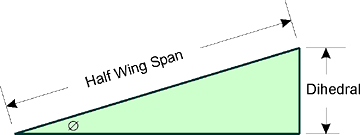
Given an angle, the wing dihedral is the amount the wingtip rises above the wing at the center of the plane.
Sine Ø = Dihedral ÷ Half Wing Span

So, a 4 degree dihedreal for a Blu Baby 33 would be sin(4 degrees) * 33/2 = 1.168.

Prop each wingtip up with a 1.2 inch block and attach along the centerline.

Source

Blu Baby Control Rods

Somebody on RC Groups asked about attaching the control rods on the Blu Baby.  Here's how I did it, with the control rods on the outside.  It  doesn't look as nice as running the rods internally, but it's a lot easier.  I wanted the control rod to be as light as possible, so I used 1mm carbon fiber rod, running through plastic coffee stirrers.

 Here's the servo cutout.  Trim the foam where the servo tabs are so that the servo will sit flush.  Run the servo wire in and attach with a very small amount of hot glue under each tab.

The servo attachment is a straightened paper clip with a Z-bend.  I put both the CF rod and the paper clip into 1.5mm shrink wrap, and added a couple of drops of CA.  Heating the shrink wrap gave a very tight, even connection between the two surfaces for the glue to bond to.  Any excess CA will drip out when heating, so be careful.


Hot glue a control horn to the rudder.  It's attached with a Hobby King 1.5mm screw mount. If you save this step for last, you can find the "natural" spot where the control rod will go.

 You can see here that the control rod runs through two plastic coffee stirrers that have been taped together and trimmed to length.  I attached them to the plane with three spots of hot glue, the tiniest I could use that still held the coffee stirrers firmly in place.

Green note:  These are recycled coffee stirrers that were used to stir organic half and half into free-trade organic coffee!
 Here's the inside of the plane, showing that the servos are flush mounted against the monobody.  It also shows how tight the inside is on a Blu Baby 33 with one inch monobody, which is why this technique is so much easier than running the control rods on the inside.  Later I'll try a Blu Baby with 2 inch monoblock, where I can actually fit my fingers inside.
Attach the elevator opposite the rudder.

Sunday, May 15, 2011

Elevon / V-Tail Mixing

Here's what an Elevon or V-Tail/ mixer does.  You can do it with your radio if it has that feature, or with an electronic hardware mixer.  Here's the HobbyKing Mixer in action:


If you're hardcore old school, you can do pure hardware mixing with this Dubro V-Tail kit ("23 piece kit").  NightFlyyer has a nice video (where??) showing one of his classic planes with hardware mixing.


Elevon Action

The elevator control will move both elevons equally up or down.  When the aileron control is centered, pull the elevator back, then push it forwards.  You will see the elevons go up, then down.  The plane will be level across the wings, and pitch up and down.

The aileron control will move the elevons in the opposite direction.  With the elevator centered, move the aileron control left, then right.  When the stick is to the left, you will see the left elevon move up and the right elevon move down.  When the stick is to the right, the left elevon will be down and the right elevon will be up.  The plane will be level, rolling left and right.

When both the elevator and aileron move, the elevons combine the motion of the two.  For example, pull the aileron left; you will see the left/right elevons move up/down.  Keeping the aileron left, pull the elevator back.  Both elevons will move up the same amount, keeping the deflection set by the aileron.

Motion Rules:
  • elevator back: elevons up
  • elevator forward: elevons down
  • aileron left: left elevon up, right elevon down
  • aileron right: right elevon up, left elevon down
Elevon Equivalence

The same calculations for translating aileron/elevator to elevon wing surfaces will translate joystick controls to tank-style left/right wheel/tread motion.

Calculating Elevon Motion

update: I moved this to its own post, here.

Saturday, May 14, 2011

Arcticopter II: test videos

Hooray, the Arcticopter II looks like it's going to be a fine flyer.  Powerful motors, it can probably shoot to a hundred feet in a couple of seconds.

More test results to come, but here's a couple of shots of the first test session.

 Here are the original flight tests.  We've substituted the wiffle ball landing gear... it's really nice if you can handle the weight.  As you can see from the videos, weight is not a problem for this model... it took all the control we had not to shoot it straight up into the trees and beyond.  One thing to investigate: using heli mode on the radio so as to set a throttle curve.  We fiddled with that a little bit, but then couldn't take the unit off of safety because we had displaced the zero setting off the power curve.


Here was our very first test.  Notice how the rightmost leg seems to stick to the ground?  That's the sure sign you've got a motor running backwards!  This also shows the original wire legs.


Before we did all of this of course we tested the electronics without blades.  It always sounds like an assembly line of dentists to my ears.

Arcticopter II: Build part 2

Picking up the build the next day.

We used an extra platter to keep the wiring together.   We used four extra standoffs (is that what these things are called?)  Here's some notes about how they're attached.

The tabs have been trimmed from two of the standoffs, so that they're acting as spacers but don't need to be attached to the platter.  this makes it easier to set up and remove.

Note that we cut off the tabs on two of the standoffs.  Originally we did this because they were two-tab standoffs lining up with three-tab holes, but it turned out to be a very nice setup.
    We filed out the tab holes on the top platter so that it seats and unseats smoothly.  We'll use some thin bolts to hold things together.

    We'll try putting another platter on top (or below?) to cover up the stabilization board.
    The standoffs are placed in the holes that are offset from the arms, allowing unobstructed access for the wiring.

    We got lucky... the motor wiring, the ESC wiring, and the Wago connectors were the perfect size so that everything fit without having to add any extra wir


    The KKBoard is being moved between the Arcticopters 1, 2, and (soon) 3 until some more boards arrive, so it's attached to a carrier board.

    The KKBoard is sitting on a double layer of 3M doublesided foam tape, and attached to the carrier with zip ties.


    For now we've got everything taped together, but we'll figure out how to attach it so that it's stable, firm, and easy to move.


    HINT: don't mess up and mount your board at 90 degrees to what it should be.  As soon as you apply the smallest amount of power it will attempt to correct itself by instantly flipping upside down!


    We didn't have a lot of luck with the music wire legs... Since the weight should not be an issue with the motors we've got, we tried zip-tying wiffle balls under the motors.  The motor mounts make a natural cradle that holds it in place.  Use some pliers to pull the zip tie tight and it's very stable.  This worked pretty well.  I'll get some numbers on the wiffle ball weight.

    I'll try the music wire legs on Arcticopter III which will be much smaller and as light as I can get it.

    A KFC bowl is the perfect size for covering the platter.  Thanks Colonel, this flight's for you!


    Flight videos in the next post!

    Arcticopter II: Build part 1

    Here's the basic RadicalRC kit assembly.  It's really nice. We're using the carbon fiber arms.  Everything fit together nicely, and we glued it up with medium CA.  Hot glue seems to be just fine to center the arms.
     
    Wago connectors for power distribution, as noted here.  These have been great on the Arcticopter I.  These motors are a lot bigger, so it will be interesting to see the power draw through the connector.  The motors max out at 375 watts each, but this thing will be at airliner altitudes if you keep that much power for too long.


    Here's the basic frame with motors attached.  It's very light and solid.  I had originally been a bit skeptical about the 10mm arms but am now a big fan.


    The motor had an extended shaft.  Drilling through the carbon fiber arm was a no-go, so Andreas tried every saw in his shop to cut off the motor shaft.  None of them even scratched the shaft, which is why every RC toolbox should include an angle grinder with cutoff wheel.


    Cover it up with tape to keep crud out of the windings and bearings, and clamp onto the motor shaft.
    Dont' forget safety goggles!  Next time I'm going to try it with a (much smaller) Dremel cutoff wheel.  If that doesn't work then I'll just borrow Andreas' big cutting wheel.

    There's a little sliver left on the shaft.  You can trim it off if you're so minded, but it's not necessary.
    A lovely fit!  This is a shot of the lower arm, where the shaft came close to fitting... it was a bit easier to get a good picture.


    Here's how the motors are mounted.  The bolts have "blue" removable threadlock.


    Say hello to our little 4S friend.  One goal of Arcticopter II is to measure the payload size that can be reasonably handled.  The final Arcticopter will need to carry Josh's full-sized Canon DSLR... we probably should find out the target weight.

    As you'll see in the flight videos, there's no problem blasting into the air.  Andreas has told me it's pretty good with 3S as well.


    For some unknown reason, the Hobby King shipment did not include the expected fasteners.  Fortunately the local Ace has a nice selection of metric fasteners.  Judging by the price, they're made from an allow of platinum, iridium and gold.


    The build went really smoothly, and the Radical RC kit was nice to work with. Andreas had glued up the  pieces and attached the motors... Everything on this page we did in an evening.

    Continued in next post...

    Friday, May 13, 2011

    Blade mSR notes

    Training Wheels

    Definitely get this set of training wheels if you're just starting out.  It will pay for itself in no time.  You can drop the unit from quite a distance, and it will bounce on the training wheels with no problem. They're about the width of the blades as well, so it can keep you from grinding your blades into the wall when you get too close.  I like keeping them on all the time now... the X arms are neat looking IMHO.

    They're about $4.  Of course, I didn't have anything else to order, so I also paid $6 shipping.  They should put a note about these on the mSR product page.

            EFLH3023 Carbon Fiber Training Gear Set: Blade MCX, MCX2, MSR

    I secured the legs with a drop of CA.  I've bounced the thing enough times to make the white foam balls become loose.  CA (a very tiny drop) worked to put them back in order.  When you're gluing the legs, be sure you've got the tiny rubber bands in place, and DONT let them  fall into the glue.  Tape them up until the glue is dry.  I didn't do this, but a bit of black thread works nicely to hold everything in position.

    Transmitter

    I'm using my DX6i, so I dialed in some expo which made it much more manageable as I was learning.

    Book

    J. Salt has written a number of useful (by all accounts) helicopter ebooks.  I bought a copy of Getting the Most out of your Blade mSR and 120 SR and learned a lot about helicopters in general as well as some nice tuning and radio setup tips.

    Battery

    I really like the Turnigy Nanotech 138 mAh battery with this unit.  It fits just right, and maintains the COG well.  I tried the 160 mAh, but it seemed like it was stretching out the battery mounts.

    Motor Replacement

    I had to replace my motor pretty early on... after I did, it flew a lot better.  Here's the motor:

        EFLITE BLADE MSR EFLH3003 CORELESS MAIN MOTOR W/ PINION

    I got it from this ebay vendor:

            http://myworld.ebay.com/38oceanss/?_trksid=p4340.l2559

    A lot of people order the replacement motor for the Parkzone Sukhoi.

    People have reported using the HobbyKing replacement motor for the Solo Pro 2.  You need to keep the old pinion and swap it out.  It's pretty reasonable, about $4 and 17g shipping weight. I'm going to get one on my next order and keep it as a spare.

    Wednesday, May 11, 2011

    Idea: ArduPilot Differential GPS

    Update


    Fail... lots of people have thought of this idea and it won't work.


    Executive Summary
    • Hook a GPS to GCS.
    • GCS calculates GPS difference.
    • GCS transmits GPS correction over xbee MAVLINK connection
    • ArduCopter Stabilize mode gets very fine resolution.

    Background

    I was just reading the ArduCopter 2.0 docs and saw this:

    The quad should stay in a 4-5 meter diameter "circle" around the target position.

    I recalled an old TV show where somebody used differential GPS (hereafter DGPS... is that a common name?) to track glacier movement... they had DGPS receivers planted across the ice, and a DGPS transmitter attached to rock.  I recall being impressed that they were able to get 1-inch resolution.

    I googled around for DGPS products -- wouldn't it be neat if you could just buy something and have your ArduCopter hover with that kind of resolution! -- but found out a couple of things:

    • DGPS seems pretty common in the GIS world.
    • the definiton of "highly affordable" DGPS systems was about $15k.  Yikes!
    • "portable" DPGS receivers were touted as being easy to carry around by a single person.
    • DGPS seems to work by sending the sideband correctional signal over some kind of modem.
    • "normal" GPS receivers won't benefit from a DGPS transmitter.

    Idea

    So, I had an idea for implementing DGPS in the ArduPilot/ArduCopter world.
    • Hook up a GPS unit to your ground control station (GCS).  This could be any GPS unit... You could use a hand-held receiver with USB, make a custom arduino-based unit, etc.  The purpose of this unit is to be near the GCS and feed a love GPS signal of the GCS's current position.
    • When setting up the GCS, allow an absolute current position to be entered.
    • Add a MAVLINK message outbound from the GCS to the plane(s), broadcasting the difference in measured and specified absolute position and altitude.
    • When in stable mode, the ArduPilot software takes the DGPS correction into account if it is available.
    • Super Precision Stable Mode!

    Saturday, May 7, 2011

    Turnigy 9x mixing for ArduPilot Mega

    Tom Paton deserves a PhD in obscure radio settings for figuring out how to mix Turnigy 9x mode switches:
            http://rcav.posterous.com/programming-an-ardupilot-mode-switch-for-turn
    He has a great writeup explaining the details of what he did... here's my quick-ref version.

    ArduPilot Mega Functionality

           THR-CUT    F-MODE    POS        FUNCTION
               FWD    N           0        manual
                      1           1        stabilized
                      2           2        fly-by-wire-a
              BACK    N           3        auto
                      1           4        loiter
                      2           5        rtl

    Basic Idea

    • Set the Throttle Hold Button to control Channel 5.
    • Add a mix, such that putting the F-MODE into NORM position subtracts 20.
    • Likewise, for F-MODE in position 1, subtracts 50.
    • Likewise, for F-MODE in position 2, subtracts 100.
    • This gives us 6 discrete values that will be broadcast on channel 5.
    • These 6 values map to the APM control function values.

      Setting The Mix
      • Set Channel 5 to Throttle Hold
                [FUNC SETTING] [AUX-CH]
                      CH5    THRO-HOLD
      • Set mixes 1-3
                [FUNC SETTING] [PROG MIX]

                        MIX1    MIX2    MIX3
                STATE     ACT    ACT    ACT
                MASTER    GYR    GYR    GYR
                SLAVE     FLP    FLP    FLP
                OFFSET    000    000    000
                UPRATE   -020   -050   -100
                DNRATE   -020   -050   -100
                SW        ID2    ID1    NOR
         
      • Check the Settings with the Display Menu.  There should be 6 discrete values.
                [FUNC SETTING] [DISPLAY]
       Further Mixing Information

      The manual has a unique perspective on mixing.


        Ardupilot Mega 2.1, Happy Killmore Ground Control

        Getting the hang of this... here's the latest APM.


        Still to to on Turnigy 9x:
        • figure out failsafe
        • figure out mixing, so 3-way switch can control

        Monday, May 2, 2011

        My Servo Testbed

        While fiddling around with the Ardupilot Mega it was handy to plug in servos to see if everything was behaving as expected.  Having a big bundle of loose servos wiggling around made it troublesome to see exactly which one(s) were moving. I hotglued some to a base, making it easier to see what servos were moving, and how much.


        The Fleet: Hawk Sky Notes

         Links
        Build Notes
        Microjet V3 specs
        • Li-Po Battery: 2 / 3 cells
        • RPM per volt : 2200
        • Poles: 14
        • No Load Current / 10V: 2.05A
        • Max Current: 30A/60 sec
        • Dimension: 27.5x26 
        • Shaft: 3.17mm
        • Weight: 34g
        • Recommended Max Propeller: 6x4 See Chart below
        • Recommended Model Weight: 200 - 500g (7oz to 22oz)

        Gyro in Plane Notes

        RCGroups Threads
        Videos
        Small Cheap Gyro
        Articles

        TODO:
        fill out some more information, try it out sometime